Nissan Murano Z50 (2004 year). Manual - part 48
RADIATOR (ALUMINUM TYPE)
CO-19
C
D
E
F
G
H
I
J
K
L
M
A
CO
Revision: 2004 November
2004 Murano
4.
Make sure that the rim is completely crimped down.
5.
Make sure that there is no leakage.
Refer to
INSPECTION
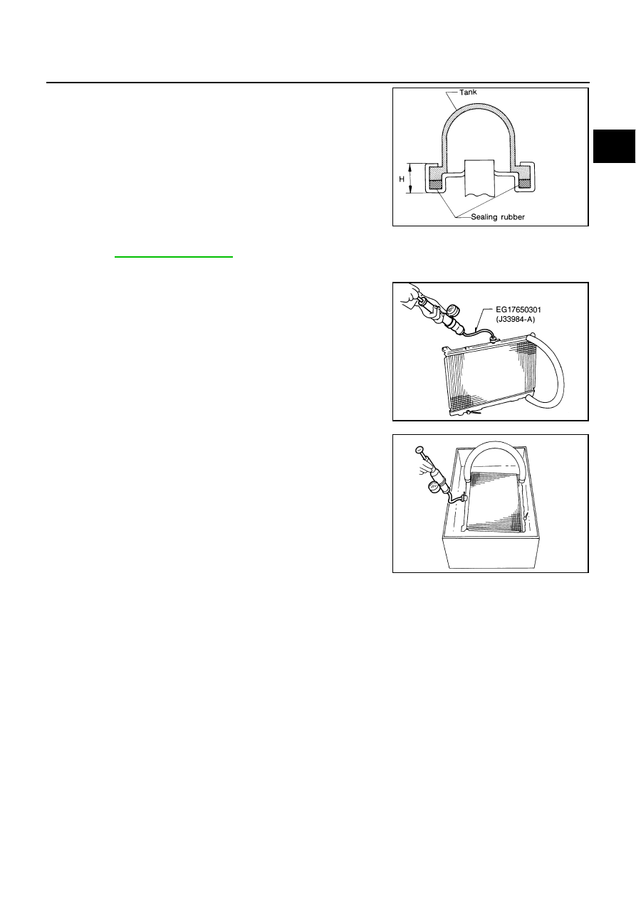
1.
Apply pressure with radiator cap tester adapter [SST] and radia-
tor cap tester (commercial service tool).
WARNING:
To prevent the risk of hose coming undone while under
pressure, securely fasten it down with hose clamp.
CAUTION:
Attach hose to CVT fluid cooler to seal its inlet and outlet.
2.
Check for leakage by soaking radiator in water container with
the testing pressure applied.
Standard height “H”
: 8.0 - 8.4 mm (0.315 - 0.331 in)
SLC554A
Testing pressure
: 157 kPa (1.6 kg/cm
2
, 23 psi)
SLC933-A
SLC934