Nissan Murano Z50 (2004 year). Manual - part 22
NAVIGATION SYSTEM
AV-163
C
D
E
F
G
H
I
J
L
M
A
B
AV
Revision: 2004 November
2004 Murano
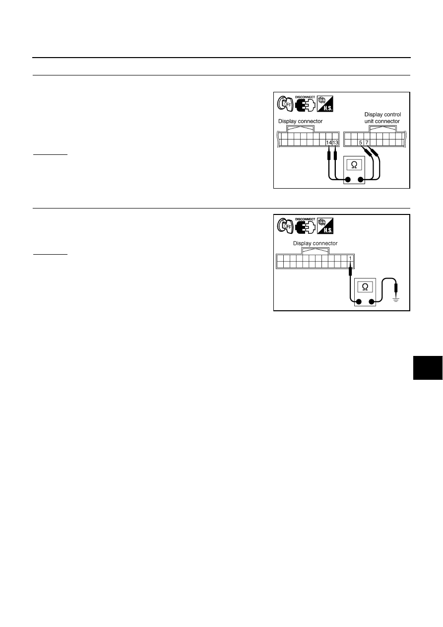
5.
CHECK HARNESS
1.
Disconnect display control unit connector.
2.
Check continuity between display harness connector M38 termi-
nals 13 (P), 14 (P/L) and display control unit harness connector
M42 terminals 5 (P), 7(P/L).
OK or NG
OK
>> Replace display control unit.
NG
>> Repair harness or connector.
6.
CHECK GROUND CIRCUIT
Check continuity between display harness connector M38 terminal 1
(B) and ground.
OK or NG
OK
>> INSPECTION END
NG
>> Repair harness or connector.
13 – 5
: Continuity should exist.
14 – 7
: Continuity should exist.
SKIB0449E
1 – Ground
: Continuity should exist.
SKIB0451E