Nissan Murano Z50 (2003 year). Manual - part 286


  Index      Manuals     Nissan Murano Z50 (2003 year) - Service and Repair Manual


Search            copyright infringement  


Content      ..     284      285      286      287     ..


Nissan Murano Z50 (2003 year). Manual - part 286


WW-48

FRONT WIPER AND WASHER SYSTEM

Revision; 2004 April

2003 Murano

INSTALLATION

1.

Install wiper motor and linkage to the vehicle.

2.

Connect wiper motor assembly to the connector. Turn wiper switch ON to operate wiper motor, then turn
wiper switch OFF (auto stop).

3.

Attach washer tube to washer tube joint.

4.

Install cowl top cover. Refer to 

EI-21, "COWL TOP"

  in “EI” section.

5.

Install wiper arms. Refer to 

WW-47, "Removal and Installation of Front Wiper Arms, Adjustment of Wiper

Arms Stop Location"

CAUTION:

Do not drop the wiper motor or cause it to contact other parts.

Check grease conditions of the motor arm and wiper link joint (at retainer side). Apply grease if
necessary.

Disassembly and Assembly of Front Wiper Motor and Linkage

AKS005H8

DISASSEMBLY

1.

Remove wiper link from wiper frame and the motor arm.

2.

Remove wiper motor mounting bolts, and remove wiper motor from wiper frame.
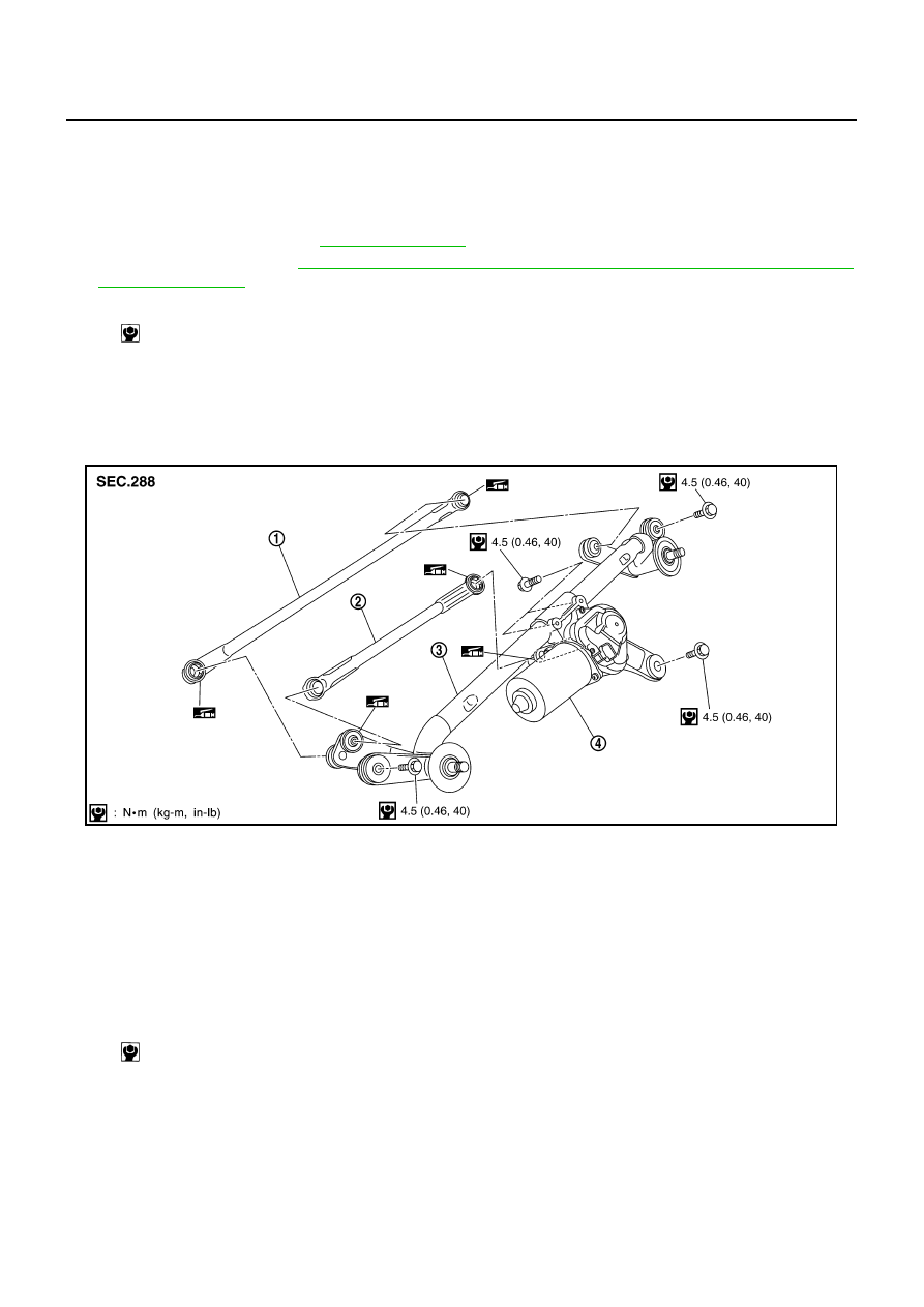
ASSEMBLY

Paying attention to the work listed below, assemble in reverse order of disassembly.

Wiper motor and linkage mounting bolts

: 4.5 N·m (0.46 kg-m, 40 in-lb)

PKIA7852E

1.

Wiper link 1

2.

Wiper link 2

3.

Wiper frame

4.

Wiper motor

Wiper motor mounting  bolts:

: 4.5 N·m (0.46 kg-m, 40 in-lb)

FRONT WIPER AND WASHER SYSTEM

WW-49

C

D

E

F

G

H

I

J

L

M

A

B

WW

Revision; 2004 April

2003 Murano

Washer Nozzle Adjustment

AKS005H9

In this model, the washer nozzle has a non-adjustment nozzle and requires no adjusting.

If necessary, ensure that washer fluid spray covers at least the area “A” and “B” as shown in the figure.
(See the illustration) 

If the above is not satisfied, confirm that the washer nozzle is installed correctly on the cowl top cover and/
or cowl top cover is installed correctly on the body. 

If they are installed correctly, and the fluid is still spraying out of the shooting target areas, replace them
with new washer nozzle and/or cowl top cover.

Unit: mm (in)

CAUTION:

Do not adjust the washer nozzle with needle pin. If attempts are
made to adjust the washer nozzle with needle pin, damage may
occur.

Spray position

h

1

h

1

h

2

h

2

L

1

L

2

A

290 (11.42)

110 (4.33)

250 (9.84)

85 (3.35)

150 (5.91)

530 (20.87)

B

200 (7.87)

90 (3.54)

230 (9.06)

120 (4.72)

75 (2.95)

445 (17.52)

PKIA2551E

PKIA2552E

WW-50

FRONT WIPER AND WASHER SYSTEM

Revision; 2004 April

2003 Murano

Washer Tube Layout

AKS005HA

Removal and Installation of Front Washer Nozzle

AKS005HB

1.

Push Washer nozzle in direction by the arrow as shown in the
figure and remove it.

2.

Remove washer tube.

INSTALLATION

Install in the reverse order of removal.

Inspection for Washer Nozzle

AKS005HD

CHECK VALVE

Blow air in the injection direction, and make sure air flows only one
way. Make sure that the reverse direction (inhale) is not possible.

PKIA2553E

PKIA2554E

PKIA2555E

FRONT WIPER AND WASHER SYSTEM

WW-51

C

D

E

F

G

H

I

J

L

M

A

B

WW

Revision; 2004 April

2003 Murano

Removal and Installation of Front Wiper and Washer Switch

AKS005HE

REMOVAL

1.

Remove instrument driver lower panel, steering column lower
cover and combination meter. Refer to 

IP-10, "INSTRUMENT

PANEL ASSEMBLY"

  in “EI” section.

2.

Disconnect  wiper and washer switch connector.

3.

Pull wiper and washer switch toward the passenger door while
pressing pawls in direction shown by the arrow in the figure, and
remove it from the base.

INSTALLATION

Install in the reverse order of removal.

Removal and Installation of Washer Tank

AKS005HF

REMOVAL

1.

Remove washer tank inlet mounting screw.

2.

Remove fender protector (front). Refer to 

EI-22, "FENDER

PROTECTOR"

  in “EI” section.

3.

Remove front bumper. Refer to 

EI-14, "FRONT BUMPER"

    in

“EI” section.

4.

Disconnect  washer pump connector.

5.

Remove washer tank mounting bolt.

6.

Remove washer tube, and remove washer tank from the vehicle.

INSTALLATION

Note the following, and install in the reverse order of removal.

CAUTION:

After installation, add water up to the upper level of the washer tank inlet, and check for water leaks.
Washer tank mounting bolt

PKIA2556E

PKIA2557E

PKIA2558E

: 4.5 N·m (0.46 kg-m, 40 in-lb)

WW-52

FRONT WIPER AND WASHER SYSTEM

Revision; 2004 April

2003 Murano

Removal and Installation of Washer Pump

AKS005HG

REMOVAL

1.

Remove fender protector (front). Refer to 

EI-22, "FENDER

PROTECTOR"

  in “EI” section.

2.

Remove the right side of front bumper. Refer to 

EI-14, "FRONT

BUMPER"

  in “EI” section.

3.

Disconnect  washer pump connector and tube.

4.

Pull out washer pump in direction shown by the arrow in the fig-
ure. Remove washer pump from washer tank.

INSTALLATION

Note the following, and install in the reverse order of removal.

CAUTION:

When installing washer pump, there should be no packing twists, etc.

Do not misconnect the front tube and the rear tube to each side when the washer tube is being
connected to the washer bump.

PKIA2560E

REAR WIPER AND WASHER SYSTEM

WW-53

C

D

E

F

G

H

I

J

L

M

A

B

WW

Revision; 2004 April

2003 Murano

REAR WIPER AND WASHER SYSTEM

PFP:28710

Components Parts and Harness Connector Location

AKS004X3

System Description

AKS004X4

Wiper switch (combination switch) is composed of a combination of 5 output terminals and 5 input termi-
nals. Terminal combination status is read by BCM (body control module) when switch is turned ON.

BCM (body control module) controls rear wiper ON and INT (intermittent) operation.

Power supplied all time

through 50 A fusible link (letter F, located in fusible link block)

to BCM (body control module) terminal 7

When ignition switch ON or START position, power is supplied

through 10 A fuse [No. 1, located in fuse block (J/B)]

to BCM (body control module) terminal 35, and

through 10 A fuse [NO. 87, located in IPDM E/R (intelligent power distribution module engine room)]

through IPDM E/R (intelligent power distribution module engine room) terminal 18

to combination switch terminal 14.

Ground is supplied

to BCM (body control module) terminal 8

through grounds E13, E26 and E28, and

to combination switch (wiper switch) terminal 12

through grounds M14 and M78.

SKIA4580E

WW-54

REAR WIPER AND WASHER SYSTEM

Revision; 2004 April

2003 Murano

REAR WIPER OPERATION

When wiper switch is in rear wiper ON position, BCM detect rear wiper ON signal by BCM wiper switch read-
ing function.
When BCM operates rear wiper motor, power is supplied 

through BCM terminal 20

to rear wiper motor 4.

Ground is supplied

to rear wiper motor terminal 2

through grounds B7 and B20. 

With power and ground supplied, the rear wiper operates.

INTERMITTENT OPERATION

The rear wiper motor operates the wiper arms at low speed approximately every 7 seconds.
When wiper switch is in rear wiper INT position, BCM detects rear wiper INT signal by BCM wiper switch read-
ing function (Refer to 

WW-7, "BCM WIPER SWITCH READING FUNCTION"

 )

When BCM operates rear wiper motor, power supplied

through BCM terminal 20

to rear wiper motor 4.

Ground is supplied

to rear wiper motor terminal 2 

through grounds B7 and B20.

With power and ground supplied, rear wiper operates at intermittent. 

AUTO STOP OPERATION

With rear wiper switch turned OFF, rear wiper motor will continue to operate until wiper arm reaches rear wiper
stopper.
Then wiper motor turns the other way and wiper arm moves once until wiper arm reaches stopper.

WASHER OPERATION

When wiper switch is in rear wiper washer position, BCM detects rear wiper washer signal by BCM wiper
switch reading function (Refer to 

WW-7, "BCM WIPER SWITCH READING FUNCTION"

 ), and combination

switch (wiper switch) ground is supplied 

through combination switch (wiper switch) terminal 11

to front and rear washer motor terminal 2 

to front and rear washer motor terminal 1 

through combination switch (wiper switch) terminal 13

to combination switch (wiper switch) terminal 12

through grounds M14 and M78.

With ground supplied, front and rear washer motor is operated.
When BCM detects that front and rear washer motor has operated for. 0.4 seconds or linger, BCM operates
rear wiper motor at low speed. 
When BCM detects washer switch is OFF, low speed operation cycles approximately 3 times and then stops.

BCM WIPER SWITCH READING FUNCTION

Refer to 

WW-7, "BCM WIPER SWITCH READING FUNCTION"

  in FRONT WIPER AND WASHER SYSTEM.

REAR WIPER AND WASHER SYSTEM

WW-55

C

D

E

F

G

H

I

J

L

M

A

B

WW

Revision; 2004 April

2003 Murano

Wiring Diagram — WIP/ R —

AKS004X5

TKWA0785E

WW-56

REAR WIPER AND WASHER SYSTEM

Revision; 2004 April

2003 Murano

TKWA0786E

REAR WIPER AND WASHER SYSTEM

WW-57

C

D

E

F

G

H

I

J

L

M

A

B

WW

Revision; 2004 April

2003 Murano

Terminals and Reference Values for BCM

AKS004X6

Terminals and Reference Values for IPDM E/R

AKS005EU

How to Proceed With Trouble Diagnosis

AKS004X7

1.

Confirm the symptoms and customer complaint.

2.

Understand operation description and function description. Refer to 

WW-53, "System Description"

 .

3.

Perform the Preliminary Check. Refer to 

WW-57, "Preliminary Check"

 .

4.

Check symptom and repair or replace the cause of malfunction.

5.

Does the warning chime operate normally? If YES: GO TO 6. If NO: GO TO 4.

6.

INSPECTION END

Preliminary Check

AKS004X8

CHECK POWER SUPPLY AND GROUND CIRCUIT

Inspection Procedure

1. 

CHECK FUSE

Check if wiper and washer fuse is blown.

Termi-

nal 

No.

Wire 

color

Signal name

Measuring condition

Reference value 

Ignition 

switch

Operation or condition

W/B

Battery power supply

OFF

Battery voltage

8

B

Ground

ON

Approx. 0V

13 

O

Rear wiper auto stop signal

ON

Rear wiper operating

Approx. 0V

Rear wiper stopped

Battery voltage

20 G

Rear wiper motor output sig-
nal

ON

Rear wiper 

switch

OFF

Approx. 0V

ON

Battery voltage

35 

R

Ignition switch (ON)

ON

Battery voltage

40

R/B

Combination switch output 2

ON

Lighting switch and wiper switch 
OFF

41

R/G

Combination switch output 3

42 

P/L

Combination switch output 4

43 

R

Combination switch output 5

47 

R/W

Combination switch output 1

48 

L/W

Combination switch input 1

ON

Lighting switch and wiper switch 
OFF

4.5V or more

49 

G/B

Combination switch input 2

ON

50 

LG/R

Combination switch input 3

ON

51

G/Y

Combination switch input 4

ON

52 

LG/B

Combination switch input 5

ON

72

O

K-LINE

SKIA1119J

Terminal 

No.

Wire 

color

Signal name

Measuring condition

Reference value

Ignition 

switch

Operation or condition

18  

R/L

Front and rear washer 
motor power supply 

ON

Battery voltage

Unit

Power source

Fuse No.

Front and rear washer motor

Ignition ON or START

87

BCM

Ignition ON or START

1

WW-58

REAR WIPER AND WASHER SYSTEM

Revision; 2004 April

2003 Murano

Refer to. 

WW-55, "Wiring Diagram — WIP/ R —"

 .

OK or NG

OK

>> GO TO 2.

NG

>> If fuse is blown, be sure to eliminate cause of malfunction before installing new fuse. Refer to 

PG-

3, "POWER SUPPLY ROUTING CIRCUIT"

 .

2. 

CHECK POWER SUPPLY CIRCUIT 

1.

Disconnect BCM connector.

2.

Check voltage between BCM harness connector and ground.

OK or NG

OK

>> GO TO 3.

NG

>> Check harness for open or short between BCM and fuse.

3. 

CHECK GROUND CIRCUIT 

Check continuity between BCM harness connector and ground.

OK or NG

OK

>> INSPECTION END

NG

>> Check harness ground circuit.

Terminals

Ignition switch position

(+)

(-)

OFF

ON

Connector

Terminal 

(Wire color)

E118

7 (W/B)

Ground

Battery voltage

Battery voltage

M35

35 (R)

0V

Battery voltage

SKIA3195E

Terminals

Continuity

Connector

Terminal (Wire color)

Ground

Yes

E118

8 (B)

SKIA3193E

REAR WIPER AND WASHER SYSTEM

WW-59

C

D

E

F

G

H

I

J

L

M

A

B

WW

Revision; 2004 April

2003 Murano

CONSULT-II Functions

AKS004X9

CONSULT-II performs the following functions communicating with BCM.

CONSULT-II OPERATION

CAUTION:

If CONSULT-II is used with no connection of CONSULT-II CONVERTER, malfunctions might be
detected in self-diagnosis depending on control unit which carry out CAN communication. 

1.

With ignition switch OFF, connect CONSULT-II and CONSULT-II
CONVERTER to data link connector, then turn ignition switch
ON.

2.

Touch “START (NISSAN BASED VHCL)”.

3.

Touch “BCM” on “SELECT SYSTEM” screen.
If “BCM” is not indicated, refer to 

GI-38, "CONSULT-II Data Link

Connector (DLC) Circuit"

 .

BCM diagnosis position

Check item, Diagnosis mode

Description

Wiper

DATA MONITOR

Displays BCM input data in real time.

ACTIVE TEST

Device operation can be checked by applying a drive signal to device.

BCM C/U

CAN DIAG SUPPORT MNTR

The result of transmit/receive diagnosis of CAN communication can be read.

PBIB1300E

SKIA3098E

SKIA6338E

WW-60

REAR WIPER AND WASHER SYSTEM

Revision; 2004 April

2003 Murano

4.

Touch “WIPER”.

DATA MONITOR
Operation Procedure

1.

Touch “WIPER” on “SELECT TEST ITEM” screen.

2.

Touch “DATA MONITOR” on “SELECT DIAG MODE” screen.

3.

Touch either “ALL SIGNALS” or “SELECTION FROM MENU” on “DATA MONITOR” screen.

4.

Touch “START”.

5.

When “SELECTION FROM MENU” is selected, touch items to be monitored. When “ALL SIGNALS” is
selected, all the items will be monitored.

6.

Touch “RECORD” while monitoring, then the status of the monitored item can be recorded. To stop
recording, touch “STOP”.

Display Item List

ACTIVE TEST
Operation Procedure

1.

Touch “WIPERS” on “SELECT TEST ITEM” screen.

2.

Touch “ACTIVE TEST” on “SELECT DIAG MODE” screen.

3.

Touch item to be tested and check operation of the selected item.

4.

During the operation check, touching “BACK” deactivates the operation.

SKIA1922E

All signals

Monitors all the items.

Selection from menu

Selects and monitors the individual item selected.

Monitor item name “operation or 

unit”

Contents

IGN ON SW

“ON/OFF”

Displays “IGN Position (ON)/OFF, ACC Position (OFF)” status as judged from ignition switch signal.

FR WIPER INT

“ON/OFF”

Displays “Front Wiper INT (ON)/Other (OFF)” status as judged from wiper switch signal.

FR WIPER LOW

“ON/OFF”

Displays “Front Wiper LOW (ON)/Other (OFF)” status as judged from wiper switch signal.

FR WIPER HI

“ON/OFF”

Displays “Front Wiper HI (ON)/Other (OFF)” status as judged from wiper switch signal.

FR WASHER SW

“ON/OFF”

Displays “Front Washer Switch (ON)/Other (OFF)” status as judged from wiper switch signal.

INT VOLUME

(1 - 7)

Displays intermittent operation dial position setting (1 - 7) as judged from wiper switch signal.

VHCL SPEED SEN

“ON/OFF”

Displays “Driving (ON)/Stopped (OFF)” status as judged from vehicle speed signal.

FR WIPER STOP

“ON/OFF”

Displays “Stopped (ON)/Operating (OFF)” status as judged from the auto-stop signal.

RR WIPER INT

“ON/OFF”

Displays “Rear Wiper INT (ON)/Other (OFF)” status as judged from wiper switch signal.

RR WIPER ON

“ON/OFF”

Displays “Rear Wiper (ON)/Other (OFF)” status as judged from wiper switch signal.

RR WASHER SW

“ON/OFF”

Displays “Rear Washer Switch (ON)/Other (OFF)” status as judged from wiper switch signal.

RR WIPER STOP

“ON/OFF”

Displays “Stopped (OFF)/Operating (ON)” status as judged from the auto-stop signal.

REAR WIPER AND WASHER SYSTEM

WW-61

C

D

E

F

G

H

I

J

L

M

A

B

WW

Revision; 2004 April

2003 Murano

Display Item List

Rear Wiper Does Not Operate

AKS004XA

1. 

REAR WIPER ACTIVE TEST 

1.

Turn to rear wiper using active test. Refer to 

WW-60, "ACTIVE TEST"

 .

2.

Make sure rear wiper operates.

OK or NG

OK

>> GO TO 6.

NG

>> GO TO 2.

2. 

CHECK REAR WIPER MOTOR CIRCUIT

1.

Turn ignition switch OFF.

2.

Disconnect BCM connector and rear wiper motor connector.

3.

Check continuity between BCM harness connector M34 terminal
20 (G) and rear wiper motor harness connector D103 terminal 4
(G).

OK or NO

OK

>>  GO TO 3.

NO

>> Repair harness or connector.

3. 

CHECK REAR WIPER MOTOR SHORT CIRCUIT

Check continuity between rear wiper motor harness connector D103
terminal 4 (G) and ground.

OK or NG

OK

>> GO TO 4.

NG

>> After repairing harness, be sure to disconnect battery

negative cable, and them reconnect it. 

Test item

Display on CONSULT-II screen

Description

Front wiper HI output

FR WIPER (HI)

Front wiper HI can be operated by any ON–OFF operation.

Front wiper LO output

FR WIPER (LO)

Front wiper LO can be operated by any ON-OFF operation.

Front wiper INT output

FR WIPER (INT)

Front wiper INT can be operated by any ON-OFF operation.

Rear wiper output

RR WIPER

Rear wiper can be operated by any ON-OFF operation.

Rear wiper operation should operate.

Continuity should exist.

SKIA3181E

Continuity should not exist.

SKIA3653E

WW-62

REAR WIPER AND WASHER SYSTEM

Revision; 2004 April

2003 Murano

4. 

CHECK GROUND CIRCUIT 

Check continuity between rear wiper motor harness connector D103
terminal 2 (B) and ground.

OK or NG

OK

>> GO TO 5.

NG

>> Repair harness or connector.

5. 

 CHECK REAR WIPER OPERATING

1.

Connect “BCM” connector and rear wiper motor connector.

2.

Select “RR WIPER” during active test. Refer to 

WW-60,

"ACTIVE TEST"

 . When rear wiper operating, check voltage

between BCM harness connector M34 terminal 20 (G) and
ground.

OK or NG

OK

>> Replace rear wiper motor.

NG

>> Replace BCM. Refer to 

BCS-36, "Removal and Installation of BCM"

 .

6. 

CHECK COMBINATION SWITCH INPUT SIGNAL

Select “BCM” on CONSULT-II. With “WIPER” data monitor, make
sure “RR WIPER INT”, “RR WIPER ON” turn ON-OFF according to
operation of wiper switch.

OK or NG

OK

>> Replace BCM. Refer to 

BCS-36, "Removal and Installa-

tion of BCM"

 .

NG

>> Replace wiper switch.

Continuity should exist.

SKIA4242E

Terminals

Voltage

(+)

(-)

Condition

Connector

Terminal 

(Wire color)

M34

20 (G)

Ground

Stopped

Approx. 0V

ON operation

Battery voltage

SKIA3183E

When wiper switch is INT position

: RR WIPER INT ON

When wiper switch is ON position

: RR WIPER ON ON

SKIA4243E

REAR WIPER AND WASHER SYSTEM

WW-63

C

D

E

F

G

H

I

J

L

M

A

B

WW

Revision; 2004 April

2003 Murano

Rear Wiper Stop Position Is Incorrect

AKS004XB

1. 

CHECK COMBINATION SWITCH INPUT SIGNAL

Select “BCM” on CONSULT-II. With “WIPER” data monitor, make
sure “RR WIPER STOP” turns ON-OFF according to wiper opera-
tion.

OK or NG

OK

>> Replace BCM. Refer to 

BCS-36, "Removal and Installa-

tion of BCM"

 .

NG

>> GO TO 2.

2. 

CHECK REAR WIPER MOTOR CIRCUIT

1.

Turn ignition switch OFF.

2.

Disconnect BCM connector and rear wiper motor connector.

3.

Check continuity between BCM harness connector M34 terminal
13 (O) and rear wiper motor harness connector D103 terminal 3
(O).

OK or NG

OK

>>  GO TO 3.

NG

>> Repair harness or connector.

3. 

CHECK REAR WIPER MOTOR SHORT CIRCUIT

Check continuity between rear wiper motor harness connector D103
terminal 3 (O) and ground.

OK or NG

OK

>> GO TO 4.

NG

>> Repair harness or connector. 

4. 

CHECK GROUND CIRCUIT 

Check continuity between rear wiper motor harness connector D103
terminal 2 (B) and ground.

OK or NG

OK

>> GO TO 5.

NG

>> Repair harness or connector.

When wiper switch is OFF

: RR WIPER STOP OFF

SKIA4244E

Continuity should exist.

SKIA4245E

Continuity should not exist.

SKIA4246E

Continuity should exist.

SKIA4242E


Content      ..     284      285      286      287     ..