Nissan Murano Z50 (2003 year). Manual - part 280


  Index      Manuals     Nissan Murano Z50 (2003 year) - Service and Repair Manual


Search            copyright infringement  


Content      ..     278      279      280      281     ..


Nissan Murano Z50 (2003 year). Manual - part 280


WT-6

ROAD WHEEL TIRE ASSEMBLY

Revision; 2004 April

2003 Murano

ROAD WHEEL TIRE ASSEMBLY

PFP:40300

Balancing Wheels (Bonding Weight Type)

AES000HD

REMOVAL

1.

Remove inner and outer balance weights from the road wheel.

CAUTION:

Be careful not to scratch the road wheel during removal.

2.

Using releasing agent, remove double-faced adhesive tape from the road wheel.

CAUTION:

Be careful not to scratch the road wheel during removal.

After removing double-faced adhesive tape, wipe clean traces of releasing agent from the road
wheel.

WHEEL BALANCE ADJUSTMENT 

If a tire balance machine has adhesion balance weight mode settings and drive-in weight mode setting,
select and adjust a drive-in weight mode suitable for road wheels.

1.

Set road wheel on wheel balancer using the center hole as a guide. Start the tire balance machine.
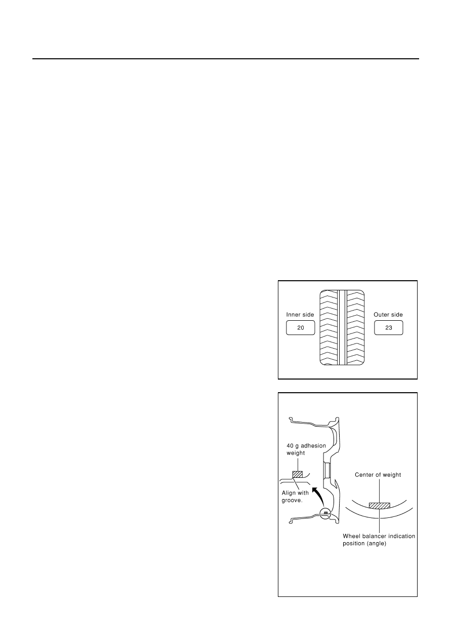
2.

When inner and outer unbalance values are shown on the wheel balancer indicator, multiply outer unbal-
ance value by 5/3 to determine balance weight that should be used. Select the outer balance weight with
a value closest to the calculated value above and install it to the designated outer position of, or at the
designated angle in relation to the road wheel.

CAUTION:

Do not install the inner balance weight before installing the outer balance weight.

Before installing the balance weight, be sure to clean the
mating surface of the road wheel.

Indicated unbalance value 

×

 5/3 = balance weight to be installed

Calculation example:
23 g (0.81 oz) 

×

 5/3 = 38.33 g (1.35 oz) = 40 g (1.41 oz) balance

weight (closer to calculated balance weight value)
Note that balance weight value must be closer to the calculated
balance weight value.
Example:
37.4 = 35 g (1.23 oz)
37.5 = 40 g (1.41 oz)

a.

Install balance weight in the position shown in the figure.

b.

When installing balance weight to road wheels, set it into the
grooved area on the inner wall of the road wheel as shown in the
figure so that the balance weight center is aligned with the wheel
balancer indication position (angle).

CAUTION:

Always use genuine Nissan adhesion balance weights.

Balance weights are unreusable; always replace with new
ones.

Do not install more than three pieces of balance weight.

SMA054D

SMA055D

ROAD WHEEL TIRE ASSEMBLY

WT-7

C

D

F

G

H

I

J

K

L

M

A

B

WT

Revision; 2004 April

2003 Murano

c.

If calculated balance weight value exceeds 50 g (1.76 oz), install
two balance weight pieces in line with each other (as shown in
the figure).

CAUTION:

Do not install one balance weight piece on top of another.

3.

Start wheel balancer again.

4.

Install drive-in balance weight on inner side of road wheel in the
wheel balancer indication position (angle).

CAUTION:

Do not install more than two balance weights.

5.

Start wheel balancer. Make sure that inner and outer residual
unbalance values are 10 g (0.35 oz) each or below.

If either residual unbalance value exceeds 10 g (0.35 oz), repeat installation procedures.

Wheel balance (Maximum allowable unbalance):

Rotation

AES000MY

After rotating the tires, adjust the tire pressure.

Retighten the wheel nuts when the vehicle has been driven for
1,000 km (600 miles) (also in cases of a flat tire, etc.).

CAUTION:

When installing wheels, tighten them diagonally by dividing
the work two to three times in order to prevent the wheels
from developing any distortion.

Maximum allowable 
unbalance

Dynamic (At rim flange)

10 g (0.35 oz) (one side)

Static (At rim flange)

20 g (0.71 oz)

SMA056D

Tightening torque of wheel nut:

 98.1 - 127 N·m (10 - 12 kg-m, 73 - 93 ft-lb)

SMA829C

WT-8

LOW TIRE PRESSURE WARNING SYSTEM

Revision; 2004 April

2003 Murano

LOW TIRE PRESSURE WARNING SYSTEM

PFP:40300

System Components

AES000HG

System Description

AES000HH

TRANSMITTER

A sensor-transmitter integrated with a valve is installed on a wheel,
and transmits a detected air pressure signal in the form of a radio
wave.

SEIA0309E

SEIA0203E

LOW TIRE PRESSURE WARNING SYSTEM

WT-9

C

D

F

G

H

I

J

K

L

M

A

B

WT

Revision; 2004 April

2003 Murano

ANTENNA

Receives the radio wave signal transmitted by the transmitter.

LOW TIRE PRESSURE WARNING CONTROL UNIT 

Reads the radio wave signal received by the antenna, and controls
the warning lamp and the buzzer operations as shown below. It also
has a judgement function to detect a system malfunction.

DISPLAY UNIT

Displays the air pressure of each tire.

After the ignition switch is turned ON, the pressure values are
not be displayed until the data of each wheel stabilizes.

SEIA0346E

SEIA0306E

Condition

Warning lamp

Buzzer

Less than 190 kPa (1.9 kg/cm

2

 , 27 psi)

[Flat tire]

ON

Sounds for 

10 sec.

System malfunction

ON

OFF

SEIA0307E

SEIA0310E

WT-10

CAN COMMUNICATION

Revision; 2004 April

2003 Murano

CAN COMMUNICATION

PFP:23710

System Description

AES000OJ

CAN (Controller Area Network) is a serial communication line for real time application. It is an on-vehicle mul-
tiplex communication line with high data communication speed and excellent error detection ability. Many elec-
tronic control units are equipped onto a vehicle, and each control unit shares information and links with other
control units during operation (not independent). In CAN communication, control units are connected with 2
communication lines (CAN H line, CAN L line) allowing a high rate of information transmission with less wiring.
Each control unit transmits/receives data but selectively reads required data only.

CAN Communication Unit For 2WD Models

AES000Y0

Go to CAN system, when selecting your CAN system type from the following table. 

×

: Applicable

TYPE 1/TYPE 2/TYPE 3/TYPE 4/TYPE 5/TYPE 6/TYPE 7/TYPE 8
System Diagram

Type1

Body type

Wagon

Axle

2WD

Engine

VQ35DE

Transmission

CVT

Brake control

ABS

VDC

Low tire pressure warning 
system

×

×

×

×

×

×

×

×

Navigation system

×

×

×

×

×

×

×

×

Automatic drive positioner

×

×

×

×

×

×

×

×

CAN communication type

1

2

3

4

5

6

7

8

9

10

11

12

13

14

15

16

SKIA4902E

CAN COMMUNICATION

WT-11

C

D

F

G

H

I

J

K

L

M

A

B

WT

Revision; 2004 April

2003 Murano

Type2

Type3

Type4

SKIA4903E

SKIA4904E

SKIA4905E

WT-12

CAN COMMUNICATION

Revision; 2004 April

2003 Murano

Type5

Type6

Type7

SKIA4906E

SKIA4907E

SKIA4908E

CAN COMMUNICATION

WT-13

C

D

F

G

H

I

J

K

L

M

A

B

WT

Revision; 2004 April

2003 Murano

Type8

SKIA4909E

WT-14

CAN COMMUNICATION

Revision; 2004 April

2003 Murano

Input/output Signal Chart

T: Transmit   R: Receive

Signals

ECM

TCM

Low 

tire 

pres-

sure 

warn-

ing 

control 

unit

Dis-
play 

unit

Dis-
play 

control 

unit

BCM

Uni-

fied 

meter 

and 
A/C 

amp.

Driver 

seat 

control 

unit

ABS 

actua-

tor and 

elec-

tric unit 

(con-

trol 

unit)

IPDM 

E/R

Engine speed signal

T

R

R

R

R

Engine status signal

T

R

Engine coolant temperature signal

T

R

CVT position indicator signal

T

R

Second position signal 

R

T

Second position indicator signal

T

R

Engine and CVT integrated control 
signal

T

R

R

T

Accelerator pedal position signal 

T

Closed throttle position signal

T

Wide open throttle position signal

T

Key switch signal

T

R

Ignition switch signal

T

R

R

P range signal

T

R

Stop lamp switch signal

R

T

Fuel consumption monitor signal

T

R

CVT self-diagnosis signal

R

T

ABS operation signal

R

T

Air conditioner switch signal

R

T

A/C compressor request signal

T

R

A/C compressor feedback signal

T

R

Blower fan motor switch signal

R

T

A/C control signal

T

T

R

R

R

T

Cooling fan speed request signal

T

R

Position lights request signal

T

R

R

Low beam request signal

T

R

Low beam status signal

R

T

High beam request signal

T

R

R

High beam status signal

R

T

Front fog lights request signal

T

R

Vehicle speed signal

R

R

T

R

R

R

R

T

R

Sleep request 1 signal

T

R

Sleep request 2 signal

T

R

Door switch signal

R

T

R

R

T

R

R

R

Turn indicator signal

T

R

CAN COMMUNICATION

WT-15

C

D

F

G

H

I

J

K

L

M

A

B

WT

Revision; 2004 April

2003 Murano

Key fob ID signal

T

R

Key fob door unlock signal

T

R

Seat belt buckle switch signal

R

T

Oil pressure switch signal

R

T

T

R

Buzzer output signal

T

R

Fuel level sensor signal

R

T

Fuel level low warning signal

R

R

T

Malfunction indicator lamp signal

T

R

ASCD SET lamp signal

T

R

ASCD CRUISE lamp signal

T

R

Input shaft revolution signal

R

T

Output shaft revolution signal

R

T

Front wiper request signal

T

R

Front wiper stop position signal

R

T

Rear window defogger switch signal

T

R

Rear window defogger control signal

R

R

R

T

Hood switch signal

R

T

Theft warning horn request signal

T

R

Horn chirp signal

T

R

Tire pressure signal

T

R

Tire pressure data signal

T

R

R

ABS warning lamp signal

R

T

Brake warning lamp signal

R

T

System setting signal

T

T

R

Parking brake switch signal

R

T

Signals

ECM

TCM

Low 

tire 

pres-

sure 

warn-

ing 

control 

unit

Dis-
play 

unit

Dis-
play 

control 

unit

BCM

Uni-

fied 

meter 

and 
A/C 

amp.

Driver 

seat 

control 

unit

ABS 

actua-

tor and 

elec-

tric unit 

(con-

trol 

unit)

IPDM 

E/R

WT-16

CAN COMMUNICATION

Revision; 2004 April

2003 Murano

TYPE 9/TYPE10/TYPE 11/TYPE 12/TYPE 13/TYPE 14/TYPE 15/TYPE 16
System Diagram

Type9

Type10

Type11

SKIA4910E

SKIA4911E

SKIA4912E

CAN COMMUNICATION

WT-17

C

D

F

G

H

I

J

K

L

M

A

B

WT

Revision; 2004 April

2003 Murano

Type12

Type13

Type14

SKIA4913E

SKIA4914E

SKIA4915E

WT-18

CAN COMMUNICATION

Revision; 2004 April

2003 Murano

Type15

Type16

SKIA4916E

SKIA4917E

CAN COMMUNICATION

WT-19

C

D

F

G

H

I

J

K

L

M

A

B

WT

Revision; 2004 April

2003 Murano

Input/Output Signal Chart

T: Transmit   R: Receive

Signals

ECM

TCM

Low 

tire 

pres-

sure 

warn-

ing 

con-

trol 

unit

Dis-
play 

unit

Dis-
play 

con-

trol 

unit

BCM

Uni-

fied 

meter 

and 
A/C 

amp.

Steer-

ing 

angle 

sen-

sor

Driver 

seat 
con-

trol 

unit

ABS 

actua-

tor 

and 

elec-

tric 

unit 

(con-

trol 

unit)

IPDM 

E/R

Engine speed signal

T

R

R

R

R

R

Engine status signal

T

R

Engine coolant temperature signal

T

R

Engine and CVT integrated control 
signal

T

R

R

T

Accelerator pedal position signal 

T

R

R

Closed throttle position signal

T

Wide open throttle position signal

T

Key switch signal

T

R

Ignition switch signal

T

R

R

P range signal

T

R

R

Stop lamp switch signal

R

T

VDC operation signal

R

T

Second position indicator signal

T

R

R

Second position signal 

R

T

Fuel consumption monitor signal

T

R

CVT self-diagnosis signal

R

T

Input shaft revolution signal

R

T

R

Output shaft revolution signal

R

T

R

Air conditioner switch signal

R

T

A/C compressor request signal

T

R

A/C compressor feedback signal

T

R

Blower fan motor switch signal

R

T

A/C control signal

T

T

R

R

R

T

Cooling fan speed request signal

T

R

Position lights request signal

T

R

R

Low beam request signal

T

R

Low beam status signal

R

T

High beam request signal

T

R

R

High beam status signal

R

T

Front fog lights request signal

T

R

Vehicle speed signal

R

R

T

R

R

R

R

T

R

Sleep request 1 signal

T

R

Sleep request 2 signal

T

R

WT-20

CAN COMMUNICATION

Revision; 2004 April

2003 Murano

Door switch signal

R

T

R

R

T

R

R

R

Turn indicator signal

T

R

Key fob ID signal

T

R

Key fob door unlock signal

T

R

Seat belt buckle switch signal

R

T

Oil pressure switch signal

R

T

T

R

Buzzer output signal

T

R

Fuel level sensor signal

R

T

Fuel level low warning signal

R

R

T

Malfunction indicator signal

T

R

ASCD SET lamp signal

T

R

ASCD CRUISE lamp signal

T

R

Front wiper request signal

T

R

Front wiper stop position signal

R

T

Rear window defogger switch signal

T

R

Rear window defogger control signal

R

R

R

T

Hood switch signal

R

T

Theft warning horn request signal

T

R

Horn chirp signal

T

R

Steering angle sensor signal

T

R

Tire pressure signal

T

R

Tire pressure data signal

T

R

R

CVT position indicator signal

T

R

R

ABS warning lamp signal

R

T

VDC OFF indicator lamp signal

R

T

SLIP indicator lamp signal

R

T

Brake warning lamp signal

R

T

System setting signal

T

T

R

Parking brake switch signal

R

T

Signals

ECM

TCM

Low 

tire 

pres-

sure 

warn-

ing 

con-

trol 

unit

Dis-
play 

unit

Dis-
play 

con-

trol 

unit

BCM

Uni-

fied 

meter 

and 
A/C 

amp.

Steer-

ing 

angle 

sen-

sor

Driver 

seat 
con-

trol 

unit

ABS 

actua-

tor 

and 

elec-

tric 

unit 

(con-

trol 

unit)

IPDM 

E/R

CAN COMMUNICATION

WT-21

C

D

F

G

H

I

J

K

L

M

A

B

WT

Revision; 2004 April

2003 Murano

CAN Communication Unit For AWD Models

AES000Y1

Go to CAN system, when selecting your CAN system type from the following table. 

×

: Applicable

TYPE 17/TYPE 18/TYPE 19/TYPE 20/TYPE 21/TYPE 22/TYPE 23/TYPE 24
System Diagram

Type17

Type18

Body type

Wagon

Axle

AWD

Engine

VQ35DE

Transmission

CVT

Brake control

ABS

VDC

Low tire pressure warning 
system

×

×

×

×

×

×

×

×

Navigation system

×

×

×

×

×

×

×

×

Automatic drive positioner

×

×

×

×

×

×

×

×

CAN system type

1

2

3

4

5

6

7

8

9

10

11

12

13

14

15

16

SKIA4918E

SKIA4919E


Content      ..     278      279      280      281     ..