Index Manuals Nissan Murano Z50 (2003 year) - Service and Repair Manual
Search copyright infringement
Content .. 276 277 278 279 ..
Nissan Murano Z50 (2003 year). Manual - part 278
TF-48
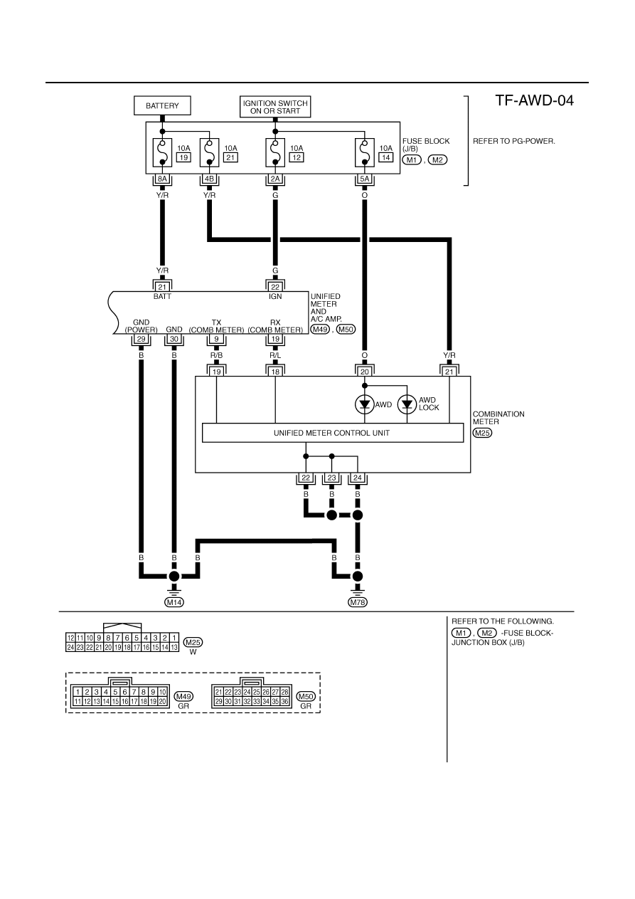
AWD SYSTEM
Revision; 2004 April
2003 Murano
TDWA0013E