Nissan Murano Z50 (2003 year). Manual - part 269
SE-96
AUTOMATIC DRIVE POSITIONER
Revision; 2004 April
2003 Murano
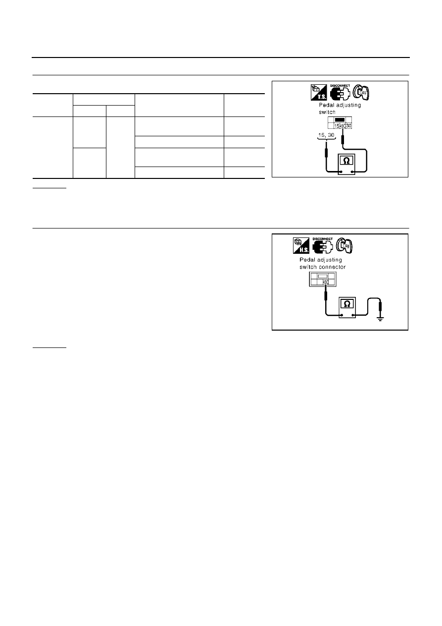
3.
CHECK PEDAL ADJUSTING SWITCH
Check continuity between pedal adjust switch as follows.
OK or NG
OK
>> GO TO 4.
NG
>> Replace pedal adjusting switch.
4.
CHECK PEDAL ADJUSTING SWITCH GROUND CIRCUIT
Check continuity between pedal adjusting switch connector B306
terminal 48C (B) and ground.
OK or NG
OK
>> Check the condition of the harness and connector.
NG
>> Replace or replace harness between pedal adjusting switch and ground.
Connector
Terminals
Condition
Continuity
(+)
(–)
B306
15
48C
Pedal adjusting switch ON
(RR operation)
Yes
Pedal adjusting switch OFF
No
30
Pedal adjusting switch ON
(FR operation)
Yes
Pedal adjusting switch OFF
No
PIIA4593E
48C (B) – Ground
: Continuity should exist.
PIIA4594E