Nissan Murano Z50 (2003 year). Manual - part 223
LT-56
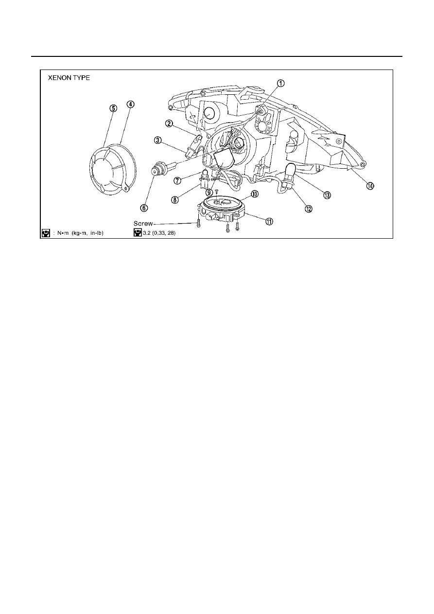
HEADLAMP - XENON TYPE -
Revision; 2004 April
2003 Murano
Disassembly and Assembly
AKS007LK
DISASSEMBLY
1.
Turn plastic cap counterclockwise and unlock it.
2.
Turn xenon bulb socket counterclockwise, and unlock it.
3.
Unlock retaining spring, and remove xenon bulb (high/low).
4.
Disconnect HID control unit connector, and remove HID control unit screws.
5.
Turn parking lamp bulb socket counterclockwise and unlock it.
6.
Remove parking lamp bulb from its socket.
7.
Turn front turn signal lamp bulb socket counterclockwise and unlock it.
8.
Remove front turn signal lamp bulb from its socket.
9.
Turn front side marker lamp bulb socket counterclockwise and unlock it.
10. Remove front side marker lamp bulb from its socket.
PKIA7851E
1.
Retaining spring
2.
Side marker lamp bulb
3.
Side marker lamp bulb socket
4.
Seal rubber
5.
Plastic cap
6.
Xenon bulb
7.
Parking lamp (Clearance lamp) bulb 8.
Parking lamp (Clearance lamp) bulb
socket
9.
Xenon bulb socket
10. Seal packing
11. HID C/U
12.
Front turn signal lamp bulb socket
13. Front turn signal lamp bulb
14. Headlamp housing assembly