Nissan Murano Z50 (2003 year). Manual - part 222


  Index      Manuals     Nissan Murano Z50 (2003 year) - Service and Repair Manual


Search            copyright infringement  


Content      ..     220      221      222      223     ..


Nissan Murano Z50 (2003 year). Manual - part 222


LT-40

HEADLAMP - XENON TYPE -

Revision; 2004 April

2003 Murano

3. 

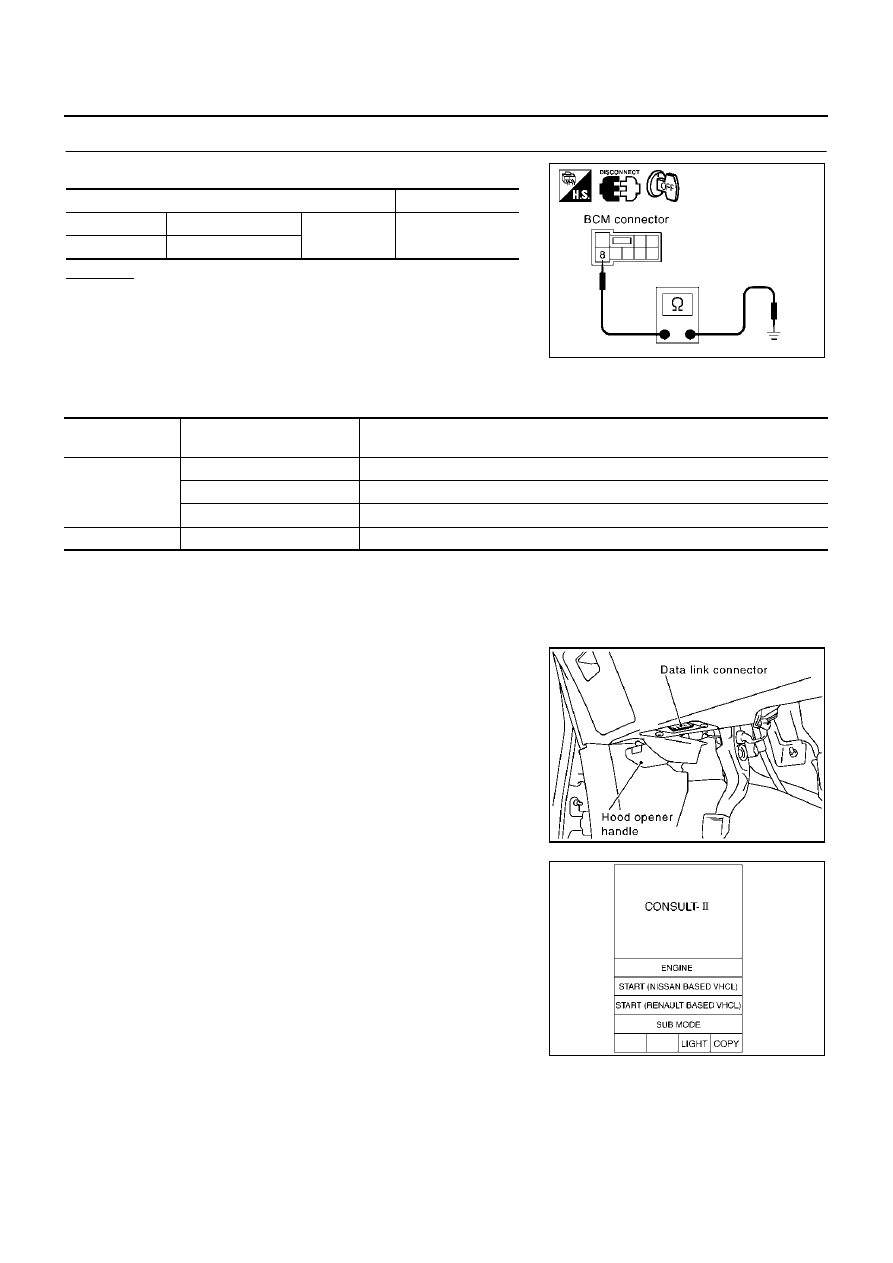
CHECK GROUND CIRCUIT

Check continuity between BCM harness connector and ground.

OK or NG

OK

>> INSPECTION END

NG

>> Check harness ground circuit.

CONSULT-II Function

AKS007L6

CONSULT-II performs the following functions communicating with BCM.

CONSULT-II BASIC OPERATION

CAUTION:

If CONSULT-II is used with no connection of CONSULT-II CONVERTER, malfunctions might be
detected in self-diagnosis depending on control unit which carry out CAN communication. 

1.

With ignition switch OFF, connect CONSULT-II and CONSULT-II
CONVERTER to data link connector, then turn ignition switch
ON.

2.

Touch “START (NISSAN BASED VHCL)”.  

Terminals

Continuity

Connector

Terminal (Wire color)

Ground

Yes

E118

8 (B)

SKIA3193E

BCM diagnosis 

part

Check item, diagnosis mode

Description

HEAD LAMP

WORK SUPPORT

Changes the setting for each function.

DATA MONITOR

Displays BCM input data in real time.

ACTIVE TEST

Operation of electrical loads can be checked by sending drive signal to them.

BCM C/U

CAN DIAG SUPPORT MNTR 

The result of transmit/receive diagnosis of CAN communication can be read.

PBIB1300E

SKIA3098E

HEADLAMP - XENON TYPE -

LT-41

C

D

E

F

G

H

I

J

L

M

A

B

LT

Revision; 2004 April

2003 Murano

3.

Touch “BCM” on “SELECT SYSTEM” screen.
If “BCM” is not indicated, refer to 

GI-38, "CONSULT-II Data Link

Connector (DLC) Circuit"

 .

4.

Touch “HEAD LAMP” on “SELECT TEST ITEM” screen.

WORK SUPPORT
Operation Procedure

1.

Touch “HEAD LAMP” on “SELECT TEST ITEM” screen.

2.

Touch “WORK SUPPORT” on “SELECT DIAG MODE” screen.

3.

Touch “BATTERY SAVER SET” on “SELECT WORK ITEM” screen.

4.

Touch “START”.

5.

Touch “CHANGE SET”.

6.

The setting will be changed and “CUSTOMIZING COMPLETED” will be displayed.

7.

Touch “END”.

Display Item List

DATA MONITOR
Operation Procedure

1.

Touch “HEAD LAMP” on “SELECT TEST ITEM” screen.

2.

Touch “DATA MONITOR” on “SELECT DIAG MODE” screen.

3.

Touch either “ALL SIGNALS” or “SELECTION FROM MENU” on “DATA MONITOR” screen.

4.

Touch “START”.

5.

When “SELECTION FROM MENU” is selected, touch individual items to be monitored. When “ALL SIG-
NALS” is selected, all the items will be monitored.

6.

Touch “RECORD” while monitoring, then the status of the monitored item can be recorded. To stop
recording, touch “STOP”.

SKIA6338E

SKIA1922E

Item

Description

CONSULT-II

Factory setting

BATTERY SAVER SET

Exterior lamp battery saver control mode can be changed 
in this mode. Selects exterior lamp battery saver control 
mode between two ON/OFF.

ON

×

OFF

All signals

Monitors all the signals.

Selection from menu

Selects and monitors individual signal.

LT-42

HEADLAMP - XENON TYPE -

Revision; 2004 April

2003 Murano

Display Item List

NOTE:
Vehicles without auto light system display this item, but cannot monitor it.

ACTIVE TEST
Operation Procedure

1.

Touch “HEAD LAMP” on “SELECT TEST ITEM” screen.

2.

Touch “ACTIVE TEST” on “SELECT DIAG MODE” screen.

3.

Touch item to be tested and check operation of the selected item.

4.

During the operation check, touching “BACK” deactivates the operation.

Display Item List

Headlamp Does Not Change To High Beam (Both Sides)

AKS007L7

1. 

HEADLAMP ACTIVE TEST

1.

Select “HEADLAMP (HI)” during active test. Refer to 

LT-42, "ACTIVE TEST"

 .

2.

Make sure headlamp high beam operation.

OK or NG

OK

>> GO TO 5.

NG

>> GO TO 2.

Monitor item

Contents

IGN ON SW

“ON/OFF”

Displays “IGN position (ON)/OFF, ACC position (OFF)” judged from the ignition switch sig-
nal.

ACC ON SW

“ON/OFF”

Displays “ACC (ON)/OFF, Ignition OFF (OFF)” status judged from ignition switch signal.

AUTO LIGHT SW

Note 

“ON/OFF”

Displays status of the lighting switch as judged from the lighting switch signal. (AUTO posi-
tion: ON/Other than AUTO position: OFF)

TAIL LAMP SW

“ON/OFF”

Displays status (lighting switch 1st position: ON/Others: OFF) of lighting switch judged 
from lighting switch signal.

HEAD LAMP SW 1

“ON/OFF”

Displays status (headlamp switch 1: ON/Others: OFF) of headlamp switch 2 judged from 
lighting switch signal. 

HI BEAM SW

“ON/OFF”

Displays status (high beam switch: ON/Others: OFF) of high beam switch judged from 
lighting switch signal.

PASSING SW

“ON/OFF”

Displays status (flash-to-pass switch: ON/Others: OFF) of flash-to-pass switch judged from 
lighting switch signal.

FR FOG SW

“ON/OFF”

Displays status (front fog lamp switch: ON/Others: OFF) of front fog lamp switch judged 
from lighting switch signal.

DOOR SW - DR

“ON/OFF”

Displays status of the driver door as judged from the driver door switch signal. (Door is 
open: ON/Door is closed: OFF)

DOOR SW - AS

“ON/OFF”

Displays status of the passenger door as judged from the passenger door switch signal. 
(Door is open: ON/Door is closed: OFF)

DOOR SW - RR

“ON/OFF”

Displays status of the rear doors as judged from the rear door switch signal. (Door is open: 
ON/Door is closed: OFF)

HEAD LAMP SW 2

“ON/OFF”

Displays status (headlamp switch 2: ON/Others: OFF) of headlamp switch 2 judged from 
lighting switch signal.

OPTICAL SENSOR

 [0 - 5V] 

Displays “ambient light (close to 5V when light/close to 0V when dark)” judged from optical 
sensor signal.

Test item

Description

TAIL LAMP

Allows tail lamp relay to operate by switching ON–OFF.

HEAD LAMP (LOW) 

Allows headlamp relay to operate by switching ON

OFF.

HEAD LAMP (HI) 

Allows headlamp relay to operate by switching ON–OFF.

FR FOG LAMP

Allows fog lamp relay to operate by switching ON–OFF.

Headlamp high beam should operate.

HEADLAMP - XENON TYPE -

LT-43

C

D

E

F

G

H

I

J

L

M

A

B

LT

Revision; 2004 April

2003 Murano

2. 

CHECK HEADLAMP CIRCUIT 

1.

Turn ignition switch OFF.

2.

Disconnect IPDM E/R connector and front combination lamp RH
and LH connector.

3.

Check continuity between IPDM E/R harness connector E7 ter-
minal 24 (L/W) and front combination lamp RH harness connec-
tor E30 terminal 1 (L/W).

4.

Check continuity between IPDM E/R harness connector E7 ter-
minal 22 (G) and front combination lamp LH harness connector
E17 terminal 1 (G).

OK or NG

OK

>> GO TO 3.

NG

>> Repair harness or connector.

3. 

CHECK HEADLAMP INPUT SIGNAL 

1.

Connect IPDM E/R connector.

2.

Select “HEADLAMP (HI)” during active test. Refer to 

LT-42,

"ACTIVE TEST"

 . When headlamp high beam is operating,

check voltage between front combination lamp RH and LH har-
ness connector and ground.

OK or NG

OK

>> GO TO 4.

NG

>> Replace IPDM E/R.

4. 

CHECK HEADLAMP GROUND 

1.

Turn ignition switch OFF.

2.

Check continuity between front combination lamp RH harness
connector E30 terminal 5 (B/W) and ground.

3.

Check continuity between front combination lamp LH harness
connector E17 terminal 5 (B/W) and ground.

OK or NG

OK

>> Replace headlamp assembly.

NG

>> Repair harness or connector.

Continuity should exist.

Continuity should exist.

SKIA4183E

Terminals

Voltage

(+)

(-)

Connector

Terminal 

(Wire color)

RH

E30

1 (L/W)

Ground Battery 

voltage

LH

E17

1 (G)

SKIA4184E

Continuity should exist.

Continuity should exist.

SKIA4188E

LT-44

HEADLAMP - XENON TYPE -

Revision; 2004 April

2003 Murano

5. 

CHECK COMBINATION SWITCH CIRCUIT 

Select “BCM” on CONSULT-II. Carry out “BCM C/U” self-diagnosis.

Displayed results of self-diagnosis

No malfunction detected>> GO TO 6.
CAN communications or CAN system>> Check BCM CAN commu-

nication system. Refer to 

BCS-34, "CAN Communica-

tion Inspection Using CONSULT-II (Self-Diagnosis)"

 .

OPEN DETECT 1 - 5>>  Combination  switch  system  malfunction.

Refer to 

LT-257, "Combination Switch Inspection

According to Self-Diagnostic Results"

 .

6. 

CHECK COMBINATION SWITCH INPUT SIGNAL 

Select “BCM” on CONSULT-II. With “HEAD LAMP” data monitor,
make sure “HI BEAM SW” turns ON-OFF linked with operation of
lighting switch.

OK or NG

OK

>> Replace BCM. Refer to 

BCS-36, "Removal and Installa-

tion of BCM"

 .

NG

>> Replace lighting switch.

Headlamp Does Not Change To High Beam (One Side)

AKS007L8

1. 

CHECK HEADLAMP CIRCUIT 

1.

Disconnect IPDM E/R connector and front combination lamp
RH or LH connector.

2.

Check continuity between IPDM E/R harness connector E7 ter-
minal 24 (L/W) and front combination lamp RH harness connec-
tor E30 terminal 1 (L/W).

3.

Check continuity between IPDM E/R harness connector E7 ter-
minal 22 (G) and front combination lamp LH harness connector
E17 terminal 1 (G).

OK or NG

OK

>> GO TO 2.

NG

>> Repair harness or connector.

LKIA0073E

When lighting switch is 
HIGH position

: HI BEAM SW ON

SKIA4193E

Continuity should exist.

Continuity should exist.

SKIA4183E

HEADLAMP - XENON TYPE -

LT-45

C

D

E

F

G

H

I

J

L

M

A

B

LT

Revision; 2004 April

2003 Murano

2. 

CHECK HEADLAMP INPUT SIGNAL 

1.

Connect IPDM E/R connector.

2.

Turn ignition switch ON.

3.

Lighting switch is turned HIGH position. 

4.

Check voltage between front combination lamp RH or LH har-
ness connector and ground.

OK or NG

OK

>> GO TO 3.

NG

>> Replace IPDM E/R.

3. 

CHECK HEADLAMP GROUND 

1.

Check continuity between front combination lamp RH harness
connector E30 terminal 5 (B/W) and ground.

2.

Check continuity between front combination lamp LH harness
connector E17 terminal 5 (B/W) and ground.

OK or NG

OK

>> Replace headlamp assembly.

NG

>> Repair harness or connector.

High Beam Indicator Lamp Does Not Illuminate

AKS007L9

1. 

CHECK BULB

Inspect bulb of high beam indicator lamp.

OK or NG

OK

>> Replace combination meter.

NG

>> Replace indicator bulb.

Headlamp Low Beam Does Not Illuminate (Both Sides)

AKS007LA

1. 

HEADLAMP ACTIVE TEST

1.

Select “HEADLAMP (LOW)” during active test. Refer to 

LT-42, "ACTIVE TEST"

 .

2.

Make sure headlamp low beam operates.

OK or NG

OK

>> GO TO 5.

NG

>> GO TO 2.

Terminals

Voltage

(+)

(-)

Connector

Terminal 

(Wire color)

RH

E30

1 (L/W)

Ground Battery 

voltage

LH

E17

1 (G)

SKIA4184E

Continuity should exist.

Continuity should exist.

SKIA4188E

Headlamp low beam should operate.

LT-46

HEADLAMP - XENON TYPE -

Revision; 2004 April

2003 Murano

2. 

CHECK HEADLAMP CIRCUIT 

1.

Turn ignition switch OFF.

2.

Disconnect IPDM E/R connector and front combination lamp RH
and LH connector.

3.

Check continuity between IPDM E/R harness connector E7 ter-
minal 27 (R/Y) and front combination lamp RH harness connec-
tor E30 terminal 4 (R/Y).

4.

Check continuity between IPDM E/R harness connector E7 ter-
minal 21 (L) and front combination lamp LH harness connector
E17 terminal 4 (L).

OK or NG

OK

>> GO TO 3.

NG

>> Repair harness or connector.

3. 

CHECK HEADLAMP INPUT SIGNAL 

1.

Connect IPDM E/R connector. 

2.

Select “HEADLAMP (LOW)” during active test. Refer to 

LT-42,

"ACTIVE TEST"

 . When headlamp low beam is operating, check

voltage between front combination lamp RH and LH harness
connector and ground.

OK or NG

OK

>> GO TO 4.

NG

>> Replace IPDM E/R.

4. 

CHECK HEADLAMP GROUND 

1.

Turn ignition switch OFF.

2.

Check continuity between front combination lamp RH harness
connector E30 terminal 5 (B/W) and ground.

3.

Check continuity between front combination lamp LH harness
connector E17 terminal 5 (B/W) and ground.

OK or NG

OK

>> Inspect headlamp harness and connectors, ballasts

(HID control unit), and xenon bulbs. Refer to 

LT-51, "Xenon Headlamp Trouble Diagnosis"

 .

NG

>> Repair harness or connector.

Continuity should exist.

Continuity should exist.

SKIA4186E

Terminals

Voltage

(+)

(-) 

Connector

Terminal 

(Wire color)

RH

E30

4 (R/Y)

Ground Battery 

voltage

LH

E17

4 (L)

SKIA4187E

Continuity should exist.

Continuity should exist.

SKIA4188E

HEADLAMP - XENON TYPE -

LT-47

C

D

E

F

G

H

I

J

L

M

A

B

LT

Revision; 2004 April

2003 Murano

5. 

CHECK COMBINATION SWITCH CIRCUIT 

Select “BCM” on CONSULT-II. Carry out “BCM C/U” self-diagnosis.

Displayed results of self-diagnosis

No malfunction detected>> GO TO 6.
CAN communications or CAN system>> Check BCM CAN commu-

nication system. Refer to 

BCS-34, "CAN Communica-

tion Inspection Using CONSULT-II (Self-Diagnosis)"

 .

OPEN DETECT 1 - 5>>  Combination  Switch  System  malfunction.

Refer to 

LT-257, "Combination Switch Inspection

According to Self-Diagnostic Results"

 .

HEAD LAMP 1 SW or HEAD LAMP 2 SW>> 

Replace 

lighting

switch.

6. 

CHECK COMBINATION SWITCH INPUT SIGNAL 

Select “BCM” on CONSULT-II. With “HEAD LAMP” data monitor,
make sure “HEAD LAMP SW 1” and “HEAD LAMP SW 2” turn ON-
OFF with operation of lighting switch.

OK or NG

OK

>> Replace BCM. Refer to 

BCS-36, "Removal and Installa-

tion of BCM"

 .

NG

>>

Replace lighting switch.

If one of “HEAD LAMP SW 1”and “HEAD LAMP SW
2” is NG, replace both BCM (Refer to 

BCS-36,

"Removal and Installation of BCM"

 ) and lighting switch.

Headlamp Low Beam Does Not Illuminate (One Side)

AKS007LB

1. 

CHECK BULB

Inspect ballasts (HID control unit) and xenon bulb of lamp which does not illuminate. Refer to 

LT-51, "Xenon

Headlamp Trouble Diagnosis"

 .

OK or NG

OK

>> GO TO 2.

NG

>> Repair malfunctioning part.

2. 

CHECK HEADLAMP CIRCUIT 

1.

Disconnect IPDM E/R connector and front combination lamp RH
or LH connector.

2.

Check continuity between IPDM E/R harness connector E7 ter-
minal 27 (R/Y) and front combination lamp RH harness connec-
tor E30 terminal 4 (R/Y).

3.

Check continuity between IPDM E/R harness connector E7 ter-
minal 21 (L) and front combination lamp LH harness connector
E17 terminal 4 (L).

OK or NG

OK

>> GOTO 3.

NG

>> Repair harness or connector.

LKIA0073E

When lighting switch is 2ND 
position

: HEAD LAMP SW 1 ON
: HEAD LAMP SW 2 ON

SKIA4194E

Continuity should exist.

Continuity should exist.

SKIA4186E

LT-48

HEADLAMP - XENON TYPE -

Revision; 2004 April

2003 Murano

3. 

CHECK HEADLAMP GROUND 

1.

Check continuity between front combination lamp RH harness
connector E30 terminal 5 (B/W) and ground.

2.

Check continuity between front combination lamp LH harness
connector E17 terminal 5 (B/W) and ground.

OK or NG

OK

>> Replace IPDM E/R.

NG

>> Repair harness or connector.

Headlamp RH Low Beam and High Beam Does Not Illuminate 

AKS007LC

1. 

CHECK BULB

Inspect ballasts (HID control unit) and xenon bulb of lamp which does not illuminate. Refer to 

LT-51, "Xenon

Headlamp Trouble Diagnosis"

 .

OK or NG

OK

>> GO TO 2.

NG

>> Repair malfunctioning part.

2. 

 CHECK HEADLAMP GROUND 

1.

Disconnect front combination lamp RH connector.

2.

Check continuity between front combination lamp RH harness
connector E30 terminal 5 (B/W) and ground.

OK or NG

OK

>> GO TO 3.

NG

>> Repair harness or connector.

Continuity should exist.

Continuity should exist.

SKIA4188E

Continuity should exist.

SKIA4188E

HEADLAMP - XENON TYPE -

LT-49

C

D

E

F

G

H

I

J

L

M

A

B

LT

Revision; 2004 April

2003 Murano

3. 

CHECK HEADLAMP CIRCUIT 

1.

Disconnect IPDM E/R connector.

2.

Check continuity between IPDM E/R harness connector E7 ter-
minal 27 (R/Y) and front combination lamp RH harness connec-
tor E30 terminal 4 (R/Y).

3.

Check continuity between IPDM E/R harness connector E7 ter-
minal 24 (L/W) and front combination lamp RH harness connec-
tor E30 terminal 1 (L/W).

OK or NG

OK

>> Replace IPDM E/R.

NG

>> Repair harness or connector.

Headlamp LH Low Beam and High Beam Does Not Illuminate 

AKS007LD

1. 

CHECK BULB

Inspect ballasts (HID control unit) and xenon bulb of lamp which does not illuminate. Refer to 

LT-51, "Xenon

Headlamp Trouble Diagnosis"

 .

OK or NG

OK

>> GO TO 2.

NG

>> Repair malfunctioning part.

2. 

  CHECK HEADLAMP GROUND 

1.

Disconnect front combination lamp LH connector.

2.

Check continuity between front combination lamp LH harness
connector E17 terminal 5 (B/W) and ground.

OK or NG

OK

>> GO TO 3.

NG

>> Repair harness or connector.

Continuity should exist.

SKIA4191E

Continuity should exist.

SKIA4192E

Continuity should exist.

SKIA4188E

LT-50

HEADLAMP - XENON TYPE -

Revision; 2004 April

2003 Murano

3. 

CHECK HEADLAMP CIRCUIT 

1.

Disconnect IPDM E/R connector.

2.

Check continuity between IPDM E/R harness connector E7 ter-
minal 21 (L) and front combination lamp LH harness connector
E17 terminal 4 (L).

3.

Check continuity between IPDM E/R harness connector E7 ter-
minal 22(G) and front combination lamp LH harness connector
E17 terminal 1(G).

OK or NG

OK

>> Replace IPDM E/R.

NG

>> Repair harness or connector.

Headlamps Do Not Turn OFF

AKS007LE

1. 

CHECK HEADLAMP TURN OFF

Make sure that lighting switch is OFF. And make sure is headlamp turns off when ignition switch is turned OFF.

OK or NG

OK

>> GO TO 3

NG

>> GO TO 2

2. 

CHECK COMBINATION SWITCH INPUT SIGNAL 

Select “BCM” on CONSULT-II. With “HEAD LAMP” data monitor,
make sure “HEAD LAMP SW 1”  and “HEAD LAMP SW 2” turns ON-
OFF linked with operation of lighting switch.

OK or NG

OK

>> Replace IPDM E/R.

NG

>> Replace lighting switch.

3. 

CHECKING CAN COMMUNICATIONS BETWEEN BCM AND IPDM E/R

IPDM E/R detects CAN communication malfunction and activates fail-safe operation. Refer to 

BCS-34, "CAN

Communication Inspection Using CONSULT-II (Self-Diagnosis)"

  and inspect CAN system.

OK or NG

OK

>> Replace IPDM E/R.

NG

>> Repair malfunctioning part.

Continuity should exist.

SKIA4189E

Continuity should exist.

SKIA4190E

When lighting switch is OFF 
position

: HEAD LAMP SW 1 OFF
: HEAD LAMP SW 2 OFF

SKIA5200E

HEADLAMP - XENON TYPE -

LT-51

C

D

E

F

G

H

I

J

L

M

A

B

LT

Revision; 2004 April

2003 Murano

CAUTION:

AKS007LF

Installation or removal of the connector must be done with the lighting switch OFF.

When the lamp is illuminated (when the lighting switch is ON), do not touch the harness, HID control unit,
inside of the lamp, or the lamp metal parts.

To check illumination, temporarily install lamp in the vehicle. Be sure to connect power at the vehicle-side
connector.

If the error can be traced directly to the electrical system, first check for items such as burned-out fuses
and fusible links, broken wires or loose connectors, pulled-out terminals, and improper connections.

Do not work with wet hands.

Using a tester for HID control unit circuit trouble diagnosis is prohibited.

Disassembling the HID control unit or harnesses (bulb socket harness, ECM harness) is prohibited.

Immediately after illumination, the light intensity and color will fluctuate, but there is nothing wrong.

When the bulb has reached the end of its lifetime, the brightness may drop significantly, it may flash
repeatedly, or the light may turn a reddish color.

Xenon Headlamp Trouble Diagnosis

AKS007LG

1. 

INSPECTION 1: CHECK XENON HEADLAMP LIGHTING

Install normal xenon bulb to corresponding xenon bulb headlamp, and check if lamp lights up.

OK or NG

OK

>> Replace xenon bulb.

NG

>> GO TO 2.

2. 

INSPECTION 2: CHECK XENON HEADLAMP LIGHTING

Install normal HID control unit to corresponding xenon headlamp, and check if lamp lights up.

OK or NG

OK

>> Replace HID control unit.

NG

>> GO TO 3.

3. 

INSPECTION 3: CHECK XENON HEADLAMP LIGHTING

Install normal xenon lamp housing assembly to corresponding xenon headlamp, and check if lamp lights up.
OK or NG

OK

>> Malfunction in starter (boosting circuit) in xenon headlamp housing (Replace xenon headlamp

housing assembly)

NG

>> INSPECTION END

LT-52

HEADLAMP - XENON TYPE -

Revision; 2004 April

2003 Murano

Aiming Adjustment

AKS007LH

PREPARATION BEFORE ADJUSTING
For details, refer to the regulations in your own country.

Before performing aiming adjustment, check the following. 

1.

Keep all tires inflated to correct pressures.

2.

Place vehicle on flat surface.

3.

Set that there is no-load in vehicle other than the driver (or equivalent weight placed in driver's position).
Coolant, engine oil filled up to correct level and full fuel tank.

LOW BEAM AND HIGH BEAM

1.

Turn headlamp low beam ON.

2.

Use adjusting screws to perform aiming adjustment.

PKIA2508E

HEADLAMP - XENON TYPE -

LT-53

C

D

E

F

G

H

I

J

L

M

A

B

LT

Revision; 2004 April

2003 Murano

ADJUSTMENT USING AN ADJUSTMENT SCREEN (LIGHT/DARK BORDERLINE)

If the vehicle front body has been repaired and/or the headlamp assembly has been replaced, check aiming.
Use the aiming chart shown in the figure.

Basic illumination area for adjustment should be within the range shown on the aiming chart.
Adjust headlamp accordingly.

CAUTION:

Be sure aiming switch is set to “0” when performing aiming
adjustment.

PKIA3034E

PKIA2547E

LT-54

HEADLAMP - XENON TYPE -

Revision; 2004 April

2003 Murano

Bulb Replacement

AKS007LI

HEADLAMP HIGH/LOW BEAM 

1.

Turn lighting switch OFF.

2.

Remove headlamp. Refer to 

LT-55, "Removal and Installation"

 .

3.

Turn plastic cap counterclockwise and unlock it.

4.

Turn bulb socket counterclockwise and unlock it.

5.

Unlock retaining spring and remove bulb from headlamp.

6.

Install in reverse order of removal.
NOTE:
After installation, perform aiming adjustment. Refer to 

LT-52,

"Aiming Adjustment"

 .  

PARKING LAMP (CLEARANCE LAMP)

1.

Turn lighting switch OFF.

2.

Remove fender protector (front). Refer to 

EI-22, "FENDER PROTECTOR"

  in “EI” section.

3.

Turn bulb socket counterclockwise and unlock it.

4.

Remove bulb from its socket.

5.

Install in reverse order of removal.

FRONT TURN SIGNAL LAMP

1.

Turn lighting switch OFF.

2.

Remove air cleaner case (when replacing LH bulb). Refer to 

EM-14, "AIR CLEANER AND AIR DUCT"

  in

“EM” section.

3.

Remove IPDM E/R (when replacing RH bulb). Refer to 

PG-46, "Removal and Installation of IPDM E/R"

  in

“PG” section (RH).

4.

Turn bulb socket counterclockwise and unlock it.

5.

Remove bulb from its socket.

6.

Install in reverse order of removal.

FRONT SIDE MARKER LAMP

1.

Turn lighting switch OFF.

2.

Remove fender protector (front). Refer to 

EI-22, "FENDER PROTECTOR"

 in "EI" section.

3.

Turn bulb socket counterclockwise and unlock it.

4.

Remove bulb from its socket.

5.

Install in reverse order of removal.

CAUTION:

After installing bulb, be sure to install plastic cap and bulb socket securely to insure watertightness.

Headlamp high/low beam
(Xenon)

: 12V - 35W (D2R)

PKIA2510E

Parking lamp (Clearance lamp)

: 12V - 3.8W

Front turn signal lamp

: 12V - 21W (amber)

Front side marker lamp

: 12V - 3.8W

HEADLAMP - XENON TYPE -

LT-55

C

D

E

F

G

H

I

J

L

M

A

B

LT

Revision; 2004 April

2003 Murano

Removal and Installation

AKS007LJ

REMOVAL

1.

Disconnect the battery negative cable.

2.

Remove front bumper. Refer to 

EI-14, "FRONT BUMPER"

    in

"EI" section.

3.

Remove headlamp mounting bolts.

4.

Remove plastics bumper bracket, then pull head lamp toward
vehicle front, disconnect connector, and remove headlamp. 

INSTALLATION

Note the following, and install in the reverse order of removal. 

NOTE:
After installation, perform aiming adjustment. Refer to 

LT-52, "Aiming Adjustment"

 .

PKIA2511E

Headlamp mounting bolt

 : 6.1 N·m (0.62 kg-m, 54 in-lb)


Content      ..     220      221      222      223     ..