Nissan Murano Z50 (2003 year). Manual - part 182
LAN-526
[CAN]
CAN SYSTEM (TYPE 15)
Revision; 2004 April
2003 Murano
10.
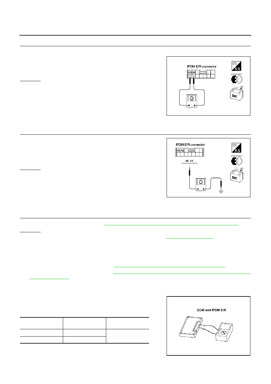
CHECK HARNESS FOR SHORT CIRCUIT
1.
Disconnect ABS actuator and electric unit (control unit) connector and IPDM E/R connector.
2.
Check continuity between IPDM E/R harness connector E9 ter-
minals 48 (L) and 49 (Y).
OK or NG
OK
>> GO TO 11.
NG
>> Check the following harnesses. If any harness is dam-
aged, repair the harness.
●
Harness between IPDM E/R and ABS actuator and
electric unit (control unit).
●
Harness between IPDM E/R and harness connector
E105.
11.
CHECK HARNESS FOR SHORT CIRCUIT
Check continuity between IPDM E/R harness connector E9 termi-
nals 48 (L), 49 (Y) and ground.
OK or NG
OK
>> GO TO 12.
NG
>> Check the following harnesses. If any harness is dam-
aged, repair the harness.
●
Harness between IPDM E/R and ABS actuator and
electric unit (control unit).
●
Harness between IPDM E/R and harness connector E105.
12.
ECM/IPDM E/R INTERNAL CIRCUIT INSPECTION
Check components inspection. Refer to
LAN-526, "ECM/IPDM E/R INTERNAL CIRCUIT INSPECTION"
OK or NG
OK
>> Connect all the connectors and diagnose again. Refer to
.
NG
>> Replace ECM and/or IPDM E/R.
IPDM E/R Ignition Relay Circuit Check
AKS006X0
Check the following. If no malfunction is found, replace the IPDM E/R.
●
IPDM E/R power supply circuit. Refer to
PG-45, "IPDM E/R Power/Ground Circuit Inspection"
.
●
Ignition power supply circuit. Refer to
PG-10, "IGNITION POWER SUPPLY - IGNITION SW. IN “ON”
Component Inspection
AKS006X1
ECM/IPDM E/R INTERNAL CIRCUIT INSPECTION
●
Remove ECM and IPDM E/R from vehicle.
●
Check resistance between ECM terminals 94 and 86.
●
Check resistance between IPDM E/R terminals 48 and 49.
48 (L) - 49 (Y)
: Continuity should not exist.
LKIA0030E
48 (L) - Ground
: Continuity should not exist.
49 (Y) - Ground
: Continuity should not exist.
LKIA0036E
Unit
Terminal
Resistance value (
Ω
)
(Approx.)
ECM
94 - 86
108 - 132
IPDM E/R
48 - 49
LKIA0037E