Nissan Murano Z50 (2003 year). Manual - part 160
LAN-174
[CAN]
CAN SYSTEM (TYPE 5)
Revision; 2004 April
2003 Murano
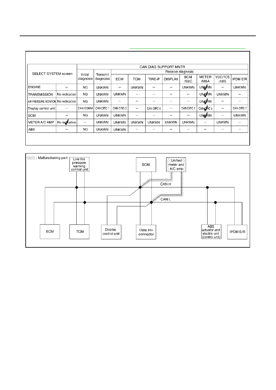
Case 9
Check unified meter and A/C amp. circuit. Refer to
LAN-182, "Unified Meter and A/C Amp. Circuit Check"
PKIB0491E
SKIA5159E
|
|
|
LAN-174 [CAN] CAN SYSTEM (TYPE 5) Revision; 2004 April 2003 Murano Case 9 Check unified meter and A/C amp. circuit. Refer to LAN-182, "Unified Meter and A/C Amp. Circuit Check" PKIB0491E SKIA5159E |