Nissan Murano Z50 (2003 year). Manual - part 151
LAN-30
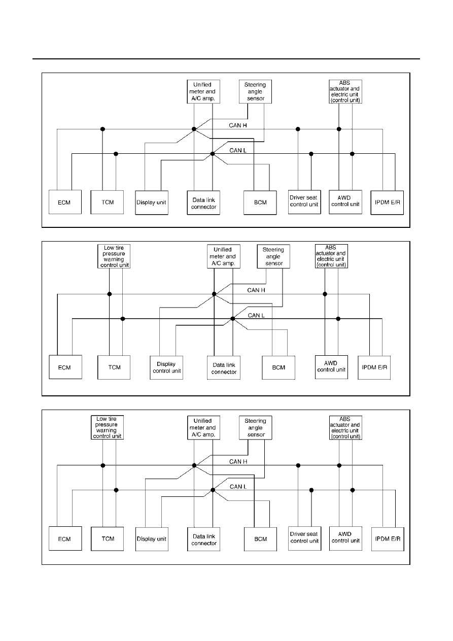
[CAN]
CAN COMMUNICATION
Revision; 2004 April
2003 Murano
●
Type28
●
Type29
●
Type30
SKIA4929E
SKIA4930E
SKIA4931E
|
|
|
LAN-30 [CAN] CAN COMMUNICATION Revision; 2004 April 2003 Murano ● Type28 ● Type29 ● Type30 SKIA4929E SKIA4930E SKIA4931E |