Nissan Murano Z50 (2003 year). Manual - part 144
FRONT DOOR GLASS AND REGULATOR
GW-59
C
D
E
F
G
H
J
K
L
M
A
B
GW
Revision; 2004 April
2003 Murano
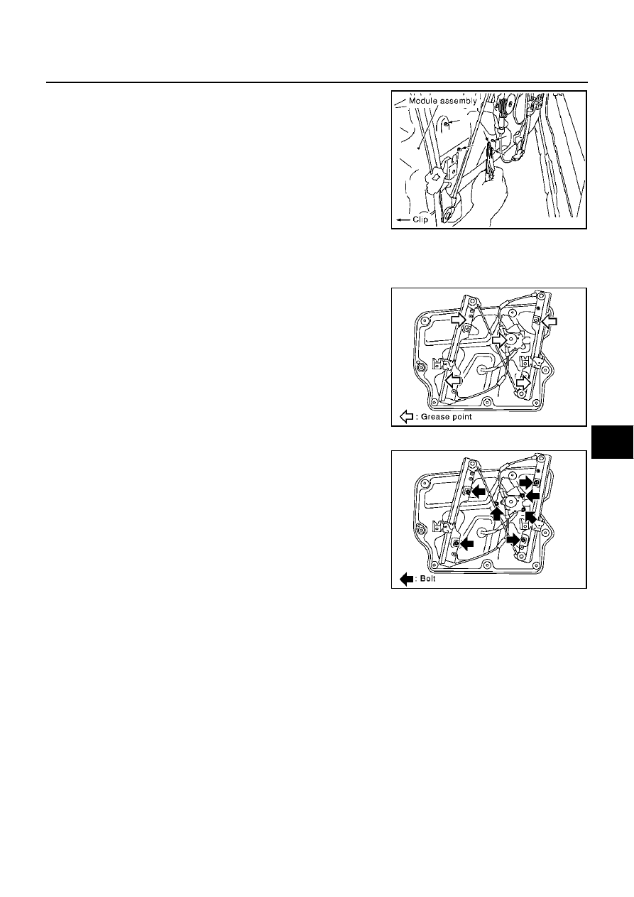
6.
Remove the mounting bolts, and remove the module assembly.
7.
Disconnect the harness connector for the module assembly, and
unclip the harness from the back.
INSTALLATION
Install in the reverse order of removal.
INSPECTION AFTER REMOVAL
Check the regulator assembly for the following items. If a malfunc-
tion is detected, replace or grease it.
●
Wire wear
●
Regulator deformation
●
Grease condition for each sliding part
The arrows in the figure show the application points of the body
grease.
DISASSEMBLY AND ASSEMBLY
Remove the power window motor and guide rail from the module
assembly.
SIIA0287E
PIIA3787E
PIIA3788E