Nissan Murano Z50 (2003 year). Manual - part 105


  Index      Manuals     Nissan Murano Z50 (2003 year) - Service and Repair Manual


Search            copyright infringement  


Content      ..     103      104      105      106     ..


Nissan Murano Z50 (2003 year). Manual - part 105


DTC P0456 EVAP CONTROL SYSTEM

EC-399

C

D

E

F

G

H

I

J

K

L

M

A

EC

Revision; 2004 April

2003 Murano

4. 

CHECK FUEL TANK VACUUM RELIEF VALVE

Refer to 

EC-655, "FUEL TANK VACUUM RELIEF VALVE (BUILT INTO FUEL FULLER CAP)"

 .

OK or NG

OK

>> GO TO 5.

NG

>> Replace fuel filler cap with a genuine one.

5. 

INSTALL THE PRESSURE PUMP

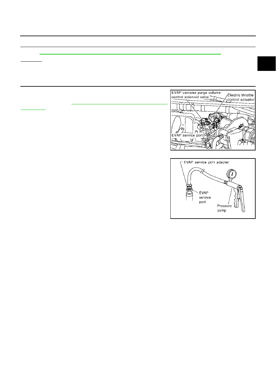
To locate the EVAP leak, install EVAP service port adapter and pres-
sure pump to EVAP service port securely. For the location of EVAP
service port, refer to 

EC-653, "EVAPORATIVE EMISSION LINE

DRAWING"

 .

NOTE:
Improper installation of the EVAP service port adapter to the EVAP service port may cause leaking.

Models with CONSULT-II>>GO TO 6.
Models without CONSULT-II>>GO TO 7.

PBIB1355E

SEF916U

EC-400

DTC P0456 EVAP CONTROL SYSTEM

Revision; 2004 April

2003 Murano

6. 

CHECK FOR EVAP LEAK

 With CONSULT-II

1.

Turn ignition switch “ON”.

2.

Select “EVAP SYSTEM CLOSE” of “WORK SUPPORT” mode with CONSULT-II.

3.

Touch “START” and apply pressure into the EVAP line until the
pressure indicator reaches the middle of the bar graph.

NOTE:

Never use compressed air or a high pressure pump.

Do not exceed 4.12 kPa (0.042 kg/cm

2

 , 0.6 psi) of pres-

sure in the system.

4.

Using EVAP leak detector, locate the EVAP leak. For the leak
detector, refer to the instruction manual for more details.
Refer to 

EC-653, "EVAPORATIVE EMISSION LINE DRAWING"

.

OK or NG

OK

>> GO TO 8.

NG

>> Repair or replace.

PEF917U

SEF200U

DTC P0456 EVAP CONTROL SYSTEM

EC-401

C

D

E

F

G

H

I

J

K

L

M

A

EC

Revision; 2004 April

2003 Murano

7. 

CHECK FOR EVAP LEAK

 Without CONSULT-II

1.

Turn ignition switch “OFF”.

2.

Apply 12 volts DC to EVAP canister vent control valve. The valve will close. (Continue to apply 12 volts
until the end of test.)

3.

Pressurize the EVAP line using pressure pump with 1.3 to 2.7 kPa (10 to 20 mmHg, 0.39 to 0.79 inHg),
then remove pump and EVAP service port adapter.

NOTE:

Never use compressed air or a high pressure pump.

Do not exceed 4.12 kPa (0.042 kg/cm

2

 , 0.6 psi) of pressure in the system.

4.

Using EVAP leak detector, locate the EVAP leak. For the leak
detector, refer to the instruction manual for more details. Refer
to 

EC-653, "EVAPORATIVE EMISSION LINE DRAWING"

 .

OK or NG

OK

>> GO TO 8.

NG

>> Repair or replace.

8. 

CHECK EVAP CANISTER VENT CONTROL VALVE

Check the following.

EVAP canister vent control valve is installed properly.
Refer to 

EC-656, "Removal and Installation"

 .

EVAP canister vent control valve.
Refer to 

EC-368, "Component Inspection"

 .

OK or NG

OK

>> GO TO 9.

NG

>> Repair or replace EVAP canister vent control valve and O-ring.

PBIB1365E

SEF200U

EC-402

DTC P0456 EVAP CONTROL SYSTEM

Revision; 2004 April

2003 Murano

9. 

CHECK IF EVAP CANISTER SATURATED WITH WATER

1.

Remove EVAP canister with EVAP canister vent control valve and EVAP control system pressure sensor
attached.

2.

Does water drain from the EVAP canister?

Yes or No

Yes

>> GO TO 10.

No (With CONSULT-II)>>GO TO 12.
No (Without CONSULT-II)>>GO TO 13.

10. 

CHECK EVAP CANISTER

Weigh the EVAP canister with the EVAP canister vent control valve and EVAP control system pressure sensor
attached.
The weight should be less than 2.1 kg (4.6 lb).

OK or NG

OK (With CONSULT-II)>>GO TO 12.
OK (Without CONSULT-II)>>GO TO 13.
NG

>> GO TO 11.

11. 

DETECT MALFUNCTIONING PART

Check the following.

EVAP canister for damage

EVAP hose between EVAP canister and vehicle frame for clogging or poor connection

>> Repair hose or replace EVAP canister.

12. 

CHECK EVAP CANISTER PURGE VOLUME CONTROL SOLENOID VALVE OPERATION

 With CONSULT-II

1.

Disconnect vacuum hose to EVAP canister purge volume control solenoid valve at EVAP service port.

2.

Start engine.

3.

Perform “PURG VOL CONT/V” in “ACTIVE TEST” mode.

4.

Touch “Qu” on CONSULT-II screen to increase “PURG VOL
CONT/V” opening to 100.0%.

5.

Check vacuum hose for vacuum when revving engine up to
2,000 rpm.

OK or NG

OK

>> GO TO 15.

NG

>> GO TO 14.

PBIB1381E

PBIB0147E

DTC P0456 EVAP CONTROL SYSTEM

EC-403

C

D

E

F

G

H

I

J

K

L

M

A

EC

Revision; 2004 April

2003 Murano

13. 

CHECK EVAP CANISTER PURGE VOLUME CONTROL SOLENOID VALVE OPERATION

 Without CONSULT-II

1.

Start engine and warm it up to normal operating temperature.

2.

Stop engine.

3.

Disconnect vacuum hose to EVAP canister purge volume control solenoid valve at EVAP service port.

4.

Start engine and let it idle for at least 80 seconds.

5.

Check vacuum hose for vacuum when revving engine up to 2,000 rpm.

OK or NG

OK

>> GO TO 16.

NG

>> GO TO 14.

14. 

CHECK VACUUM HOSE

Check vacuum hoses for clogging or disconnection. Refer to 

EC-23, "Vacuum Hose Drawing"

 .

OK or NG

OK

>> GO TO 15.

NG

>> Repair or reconnect the hose.

15. 

CHECK EVAP CANISTER PURGE VOLUME CONTROL SOLENOID VALVE

Refer to 

EC-361, "Component Inspection"

 .

OK or NG

OK

>> GO TO 16.

NG

>> Replace EVAP canister purge volume control solenoid valve.

16. 

CHECK FUEL TANK TEMPERATURE SENSOR

Refer to 

EC-299, "Component Inspection"

 .

OK or NG

OK

>> GO TO 17.

NG

>> Replace fuel level sensor unit.

17. 

CHECK EVAP CONTROL SYSTEM PRESSURE SENSOR

Refer to 

EC-378, "Component Inspection"

 .

OK or NG

OK

>> GO TO 18.

NG

>> Replace EVAP control system pressure sensor.

18. 

CHECK EVAP PURGE LINE

Check EVAP purge line (pipe, rubber tube, fuel tank and EVAP canister) for cracks or improper connection.
Refer to 

EC-653, "EVAPORATIVE EMISSION LINE DRAWING"

 .

OK or NG

OK

>> GO TO 19.

NG

>> Repair or reconnect the hose.

19. 

CLEAN EVAP PURGE LINE

Clean EVAP purge line (pipe and rubber tube) using air blower.

>> GO TO 20.

Vacuum should exist.

EC-404

DTC P0456 EVAP CONTROL SYSTEM

Revision; 2004 April

2003 Murano

20. 

CHECK EVAP/ORVR LINE

Check EVAP/ORVR line between EVAP canister and fuel tank for clogging, kink, looseness and improper con-
nection. For location, refer to 

EC-659, "ON BOARD REFUELING VAPOR RECOVERY (ORVR)"

 .

OK or NG

OK

>> GO TO 21.

NG

>> Repair or replace hoses and tubes.

21. 

CHECK RECIRCULATION LINE

Check recirculation line between filler neck tube and fuel tank for clogging, kink, cracks, looseness and
improper connection.

OK or NG

OK

>> GO TO 22.

NG

>> Repair or replace hose, tube or filler neck tube.

22. 

CHECK REFUELING EVAP VAPOR CUT VALVE

Refer to 

EC-662, "Component Inspection"

 .

OK or NG

OK

>> GO TO 23.

NG

>> Replace refueling EVAP vapor cut valve with fuel tank. 

23. 

CHECK FUEL LEVEL SENSOR

Refer to 

DI-29, "FUEL LEVEL SENSOR UNIT CHECK"

 .

OK or NG

OK

>> GO TO 24.

NG

>> Replace fuel level sensor unit.

24. 

CHECK INTERMITTENT INCIDENT

Refer to 

EC-151, "TROUBLE DIAGNOSIS FOR INTERMITTENT INCIDENT"

 .

>> INSPECTION END

DTC P0460 FUEL LEVEL SENSOR

EC-405

C

D

E

F

G

H

I

J

K

L

M

A

EC

Revision; 2004 April

2003 Murano

DTC P0460 FUEL LEVEL SENSOR

PFP:25060

Component Description

ABS004HP

The fuel level sensor is mounted in the fuel level sensor unit. The
sensor detects a fuel level in the fuel tank and transmits a signal to
the unified meter and A/C amp. The unified meter and A/C amp.
sends the fuel level sensor signal to the ECM through CAN commu-
nication line.
It consists of two parts, one is mechanical float and the other is vari-
able resistor. Fuel level sensor output voltage changes depending on
the movement of the fuel mechanical float.

On Board Diagnosis Logic

ABS004HQ

NOTE:
If DTC P0460 is displayed with DTC U1000 or U1001, first perform the trouble diagnosis for DTC U1000,
U1001.
 Refer to 

EC-159

 .

When the vehicle is parked, naturally the fuel level in the fuel tank is stable. It means that output signal of the
fuel level sensor does not change. If ECM senses sloshing signal from the sensor, fuel level sensor malfunc-
tion is detected.

DTC Confirmation Procedure

ABS004HR

NOTE:
If “DTC Confirmation Procedure” has been previously conducted, always turn ignition switch “OFF” and wait at
least 10 seconds before conducting the next test.

 WITH CONSULT-II

1.

Turn ignition switch “ON”.

2.

Select “DATA MONITOR” mode with CONSULT-II.

3.

Start engine and wait maximum of 2 consecutive minutes.

4.

If 1st trip DTC is detected, go to 

EC-406, "Diagnostic Procedure"

.

 WITH GST

Follow the procedure “WITH CONSULT-II” above.

PBIB1356E

DTC No.

Trouble diagnosis name

DTC detecting condition

Possible cause

P0460
0460

Fuel level sensor circuit 
noise

Even though the vehicle is parked, a signal 
being varied is sent from the fuel level sensor 
to ECM.

Harness or connectors
(The CAN communication line is open or 
shorted)

Harness or connectors
(The sensor circuit is open or shorted)

Unified meter and A/C amp.

Fuel level sensor

SEF195Y

EC-406

DTC P0460 FUEL LEVEL SENSOR

Revision; 2004 April

2003 Murano

Diagnostic Procedure

ABS004HS

1. 

CHECK DTC WITH UNIFIED METER AND A/C AMP.

Refer to 

DI-58, "SELF-DIAGNOSTIC RESULTS"

 .

OK or NG

OK

>> GO TO 2.

NG

>> Go to 

DI-23, "Fuel Level Sensor Signal Inspection 1"

 .

2. 

CHECK INTERMITTENT INCIDENT

Refer to 

EC-151, "TROUBLE DIAGNOSIS FOR INTERMITTENT INCIDENT"

 .

>> INSPECTION END

Removal and Installation

ABS004HT

FUEL LEVEL SENSOR

Refer to 

FL-5, "FUEL LEVEL SENSOR UNIT, FUEL FILTER AND FUEL PUMP ASSEMBLY"

 .

DTC P0461 FUEL LEVEL SENSOR

EC-407

C

D

E

F

G

H

I

J

K

L

M

A

EC

Revision; 2004 April

2003 Murano

DTC P0461 FUEL LEVEL SENSOR

PFP:25060

Component Description

ABS004HU

The fuel level sensor is mounted in the fuel level sensor unit. The
sensor detects a fuel level in the fuel tank and transmits a signal to
the unified meter and A/C amp. The unified meter and A/C amp.
sends the fuel level sensor signal to the ECM through CAN commu-
nication line.
It consists of two parts, one is mechanical float and the other is vari-
able resistor. Fuel level sensor output voltage changes depending on
the movement of the fuel mechanical float.

On Board Diagnosis Logic

ABS004HV

NOTE:
If DTC P0461 is displayed with DTC U1000 or U1001, first perform the trouble diagnosis for DTC U1000,
U1001.
 Refer to 

EC-159

 .

Driving long distances naturally affect fuel gauge level.
This diagnosis detects the fuel gauge malfunction of the gauge not moving even after a long distance has
been driven.

Overall Function Check

ABS004HW

Use this procedure to check the overall function of the fuel level sensor function. During this check, a 1st trip
DTC might not be confirmed.

WARNING:

When performing following procedure, be sure to observe the handling of the fuel. Refer to 

FL-9,

"FUEL TANK"

 .

TESTING CONDITION:
Before starting overall function check, preparation of draining fuel and refilling fuel is required.

 WITH CONSULT-II

NOTE:
Start from step 11, if it is possible to confirm that the fuel cannot be drained by 30   (7-7/8 US gal, 6-5/
8 Imp gal) in advance.

1.

Prepare a fuel container and a spare hose.

2.

Release fuel pressure from fuel line, refer to 

EC-66, "FUEL PRESSURE RELEASE"

 .

3.

Remove the fuel feed hose on the fuel level sensor unit.

4.

Connect a spare fuel hose where the fuel feed hose was removed.

5.

Turn ignition switch “OFF” and wait at least 10 seconds then turn “ON”.

6.

Select “FUEL LEVEL SE” in “DATA MONITOR” mode with CONSULT-II.

PBIB1356E

DTC No.

Trouble diagnosis name

DTC detecting condition

Possible cause

P0461
0461

Fuel level sensor circuit 
range/performance

The output signal of the fuel level sensor does 
not change within the specified range even 
though the vehicle has been driven a long dis-
tance.

Harness or connectors
(The CAN communication line is open or 
shorted)

Harness or connectors
(The sensor circuit is open or shorted)

Unified meter and A/C amp.

Fuel level sensor

EC-408

DTC P0461 FUEL LEVEL SENSOR

Revision; 2004 April

2003 Murano

7.

Check “FUEL LEVEL SE” output voltage and note it.

8.

Select “FUEL PUMP” in “ACTIVE TEST” mode with CONSULT-
II.

9.

Touch “ON” and drain fuel approximately 30   (7-7/8 US gal, 6-
5/8 Imp gal) and stop it.

10. Fill fuel into the fuel tank for 30   (7-7/8 US gal, 6-5/8 Imp gal).
11. Check “FUEL LEVEL SE” output voltage and note it.

12. Check “FUEL LEVEL SE” output voltage and confirm whether

the voltage changes more than 0.03V during step 7 to 11.
If NG, go to 

EC-408, "Diagnostic Procedure"

 .

 WITH GST

NOTE:
Start from step 8, if it is possible to confirm that the fuel cannot be drained by 30   (7-7/8 US gal, 6-5/8
Imp gal) in advance.
1.

Prepare a fuel container and a spare hose.

2.

Release fuel pressure from fuel line. Refer to 

EC-66, "FUEL PRESSURE RELEASE"

 .

3.

Remove the fuel feed hose on the fuel level sensor unit.

4.

Connect a spare fuel hose where the fuel feed hose was removed.

5.

Turn ignition switch “ON”.

6.

Drain fuel by 30   (7-7/8 US gal, 6-5/8 Imp gal) from the fuel tank using proper equipment.

7.

Confirm that the fuel gauge indication varies.

8.

Fill fuel into the fuel tank for 30   (7-7/8 US gal, 6-5/8 Imp gal).

9.

Confirm that the fuel gauge indication varies.

10. If NG, go to 

EC-408, "Diagnostic Procedure"

 .

Diagnostic Procedure

ABS004HX

1. 

CHECK DTC WITH UNIFIED METER AND A/C AMP.

Refer to 

DI-58, "SELF-DIAGNOSTIC RESULTS"

 .

OK or NG

OK

>> GO TO 2.

NG

>> Go to 

DI-23, "Fuel Level Sensor Signal Inspection 1"

 .

2. 

CHECK INTERMITTENT INCIDENT

Refer to 

EC-151, "TROUBLE DIAGNOSIS FOR INTERMITTENT INCIDENT"

 .

>> INSPECTION END

Removal and Installation

ABS004HY

FUEL LEVEL SENSOR

Refer to 

FL-5, "FUEL LEVEL SENSOR UNIT, FUEL FILTER AND FUEL PUMP ASSEMBLY"

 .

SEF195Y

DTC P0462, P0463 FUEL LEVEL SENSOR

EC-409

C

D

E

F

G

H

I

J

K

L

M

A

EC

Revision; 2004 April

2003 Murano

DTC P0462, P0463 FUEL LEVEL SENSOR

PFP:25060

Component Description

ABS004HZ

The fuel level sensor is mounted in the fuel level sensor unit. The
sensor detects a fuel level in the fuel tank and transmits a signal to
the unified meter and A/C amp. The unified meter and A/C amp.
sends the fuel level sensor signal to the ECM through CAN commu-
nication line.
It consists of two parts, one is mechanical float and the other is vari-
able resistor. Fuel level sensor output voltage changes depending on
the movement of the fuel mechanical float.

On Board Diagnosis Logic

ABS004VI

NOTE:
If DTC P0462 or P0463 is displayed with DTC U1000 or U1001, first perform the trouble diagnosis for
DTC U1000, U1001.
 Refer to 

EC-159

 .

This diagnosis indicates the former, to detect open or short circuit malfunction.

DTC Confirmation Procedure

ABS004I1

NOTE:
If “DTC Confirmation Procedure” has been previously conducted, always turn ignition switch “OFF” and wait at
least 10 seconds before conducting the next test.
TESTING CONDITION:
Before performing the following procedure, confirm that battery voltage is more than 11V at ignition
switch “ON”.

 WITH CONSULT-II

1.

Turn ignition switch “ON”.

2.

Select “DATA MONITOR” mode with CONSULT-II.

3.

Wait at least 5 seconds.

4.

If 1st trip DTC is detected, go to 

EC-410, "Diagnostic Procedure"

.

 WITH GST

Follow the procedure “WITH CONSULT-II” above.

PBIB1356E

DTC No.

Trouble diagnosis name

DTC detecting condition

Possible cause

P0462
0462

Fuel level sensor circuit 
low input

An excessively low voltage from the sensor is 
sent to ECM.

Harness or connectors
(The CAN communication line is open or 
shorted)

Harness or connectors
(The sensor circuit is open or shorted)

Unified meter and A/C amp.

Fuel level sensor

P0463
0463

Fuel level sensor circuit 
high input

An excessively high voltage from the sensor is 
sent to ECM.

SEF195Y

EC-410

DTC P0462, P0463 FUEL LEVEL SENSOR

Revision; 2004 April

2003 Murano

Diagnostic Procedure

ABS004I2

1. 

CHECK DTC WITH UNIFIED METER AND A/C AMP.

Refer to 

DI-58, "SELF-DIAGNOSTIC RESULTS"

 .

OK or NG

OK

>> GO TO 2.

NG

>> Go to 

DI-23, "Fuel Level Sensor Signal Inspection 1"

 .

2. 

CHECK INTERMITTENT INCIDENT

Refer to 

EC-151, "TROUBLE DIAGNOSIS FOR INTERMITTENT INCIDENT"

 .

>> INSPECTION END

Removal and Installation

ABS004I3

FUEL LEVEL SENSOR

Refer to 

FL-5, "FUEL LEVEL SENSOR UNIT, FUEL FILTER AND FUEL PUMP ASSEMBLY"

 .

DTC P0500 VSS

EC-411

C

D

E

F

G

H

I

J

K

L

M

A

EC

Revision; 2004 April

2003 Murano

DTC P0500 VSS

PFP:32702

Description

ABS004I4

NOTE:
If DTC P0500 is displayed with DTC U1000 or U1001, first perform the trouble diagnosis for DTC U1000,
U1001.
 Refer to 

EC-159, "DTC U1000, U1001 CAN COMMUNICATION LINE"

 .

The vehicle speed signal is sent to the unified meter and A/C amp. from the VDC/TCS/ABS control unit (mod-
els with VDC) or ABS actuator and electric unit (control unit) (models without VDC) by CAN communication
line. The unified meter and A/C amp. then sends a signal to the ECM by CAN communication line.

On Board Diagnosis Logic

ABS004I5

DTC Confirmation Procedure

ABS004I6

CAUTION:

Always drive vehicle at a safe speed.

NOTE:
If “DTC Confirmation Procedure” has been previously conducted, always turn ignition switch “OFF” and wait at
least 10 seconds before conducting the next test.
TESTING CONDITION:
Steps 1 and 2 may be conducted with the drive wheels lifted in the shop or by driving the vehicle. If a
road test is expected to be easier, it is unnecessary to lift the vehicle.

 WITH CONSULT-II

1.

Start engine (VDC switch “OFF”).

2.

Read “VHCL SPEED SE” in “DATA MONITOR” mode with CONSULT-II. The vehicle speed on CONSULT-
II should exceed 10 km/h (6 MPH) when rotating wheels with suitable gear position.
If NG, go to 

EC-412, "Diagnostic Procedure"

 .

If OK, go to following step.

3.

Select “DATA MONITOR” mode with CONSULT-II.

4.

Warm engine up to normal operating temperature.

5.

Maintain the following conditions for at least 60 consecutive sec-
onds.

6.

If 1st trip DTC is detected, go to 

EC-412, "Diagnostic Procedure"

.

DTC No.

Trouble diagnosis name

DTC detecting condition

Possible cause

P0500
0500

Vehicle speed sensor

The almost 0 km/h (0 MPH) signal from 
vehicle speed sensor is sent to ECM 
even when vehicle is being driven.

Harness or connectors
(The CAN communication line is open or 
shorted)

Harness or connectors
(The vehicle speed signal circuit is open or 
shorted)

Wheel sensor

Unified meter and A/C amp.

VDC/TCS/ABS control unit (models with VDC)

ABS actuator and electric unit (control unit) 
(models without VDC)

ENG SPEED

1,600 - 6,000 rpm

COOLAN TEMP/S

More than 70

°

C (158

°

F)

B/FUEL SCHDL

5.5 - 31.8 msec

Selector lever

Except "P" or "N" position

PW/ST SIGNAL

OFF

SEF196Y

EC-412

DTC P0500 VSS

Revision; 2004 April

2003 Murano

Overall Function Check

ABS004I7

Use this procedure to check the overall function of the vehicle speed sensor circuit. During this check, a 1st
trip DTC might not be confirmed.

 WITH GST

1.

Lift up drive wheels.

2.

Start engine.

3.

Read vehicle speed sensor signal in “MODE 1” with GST.
The vehicle speed sensor on GST should be able to exceed 10 km/h (6 MPH) when rotating wheels with
suitable gear position.

4.

If NG, go to 

EC-412, "Diagnostic Procedure"

 .

Diagnostic Procedure

ABS004I8

1. 

CHECK DTC WITH VDC/TCS ABS CONTROL UNIT (MODELS WITH VDC) OR ABS ACTUATOR AND 

ELECTRIC UNIT (CONTROL UNIT) (MODELS WITHOUT VDC)

Refer to 

BRC-98, "TROUBLE DIAGNOSIS"

  (models with VDC) or 

BRC-31, "TROUBLE DIAGNOSIS"

  (mod-

els without VDC).

OK or NG

OK

>> GO TO 2.

NG

>> Repair or replace.

2. 

CHECK DTC WITH UNIFIED METER AND A/C AMP.

Refer to 

DI-4, "COMBINATION METERS"

 .

>> INSPECTION END

DTC P0506 ISC SYSTEM

EC-413

C

D

E

F

G

H

I

J

K

L

M

A

EC

Revision; 2004 April

2003 Murano

DTC P0506 ISC SYSTEM

PFP:23781

Description

ABS004I9

NOTE:
If DTC P0506 is displayed with other DTC, first perform the trouble diagnosis for the other DTC.
The ECM controls the engine idle speed to a specified level through the fine adjustment of the air, which is let
into the intake manifold, by operating the electric throttle control actuator. The operating of the throttle valve is
varied to allow for optimum control of the engine idling speed. The crankshaft position sensor (POS) detects
the actual engine speed and sends a signal to the ECM.
The ECM controls the electric throttle control actuator so that the engine speed coincides with the target value
memorized in the ECM. The target engine speed is the lowest speed at which the engine can operate steadily.
The optimum value stored in the ECM is determined by taking into consideration various engine conditions,
such as during warming up, deceleration, and engine load (air conditioner, power steering and cooling fan
operation, etc.). 

On Board Diagnosis Logic

ABS004IA

DTC Confirmation Procedure

ABS004IB

NOTE:

If “DTC Confirmation Procedure” has been previously conducted, always turn ignition switch “OFF” and
wait at least 10 seconds before conducting the next test.

If the target idle speed is out of the specified value, perform “Idle Air Volume Learning”, 

EC-64

 ,

before conducting “DTC Confirmation Procedure”. For the target idle speed, refer to the “Service
Data and Specifications (SDS)”, 

EC-669

 .

TESTING CONDITION:

Before performing the following procedure, confirm that battery voltage is more than 11V at idle.

Always perform the test at a temperature above 

10

°

C (14

°

F).

 WITH CONSULT-II

1.

Open engine hood.

2.

Start engine and warm it up to normal operating temperature.

3.

Turn ignition switch “OFF” and wait at least 10 seconds.

4.

Turn ignition switch “ON” again and select “DATA MONITOR”
mode with CONSULT-II.

5.

Start engine and run it for at least 1 minute at idle speed.

6.

If 1st trip DTC is detected, go to 

EC-414, "Diagnostic Procedure"

.

 WITH GST

Follow the procedure “WITH CONSULT-II” above.

DTC No.

Trouble diagnosis name

DTC detecting condition

Possible cause

P0506
0506

Idle speed control sys-
tem RPM lower than 
expected

The idle speed is less than the target idle 
speed by 100 rpm or more.

Electric throttle control actuator

Intake air leak

SEF174Y

EC-414

DTC P0506 ISC SYSTEM

Revision; 2004 April

2003 Murano

Diagnostic Procedure

ABS004IC

1. 

CHECK INTAKE AIR LEAK

1.

Start engine and let it idle.

2.

Listen for an intake air leak after the mass air flow sensor.

OK or NG

OK

>> GO TO 2.

NG

>> Discover air leak location and repair.

2. 

REPLACE ECM

1.

Stop engine.

2.

Replace ECM.

3.

Perform initialization of NATS system and registration of all NATS ignition key IDs. Refer to 

BL-189, "ECM

Re-communicating Function"

 .

4.

Perform 

EC-63, "Accelerator Pedal Released Position Learning"

 .

5.

Perform 

EC-64, "Throttle Valve Closed Position Learning"

 .

6.

Perform 

EC-64, "Idle Air Volume Learning"

 .

>> INSPECTION END


Content      ..     103      104      105      106     ..