Nissan Murano Z50 (2003 year). Manual - part 89
TROUBLE DIAGNOSIS
EC-143
C
D
E
F
G
H
I
J
K
L
M
A
EC
Revision; 2004 April
2003 Murano
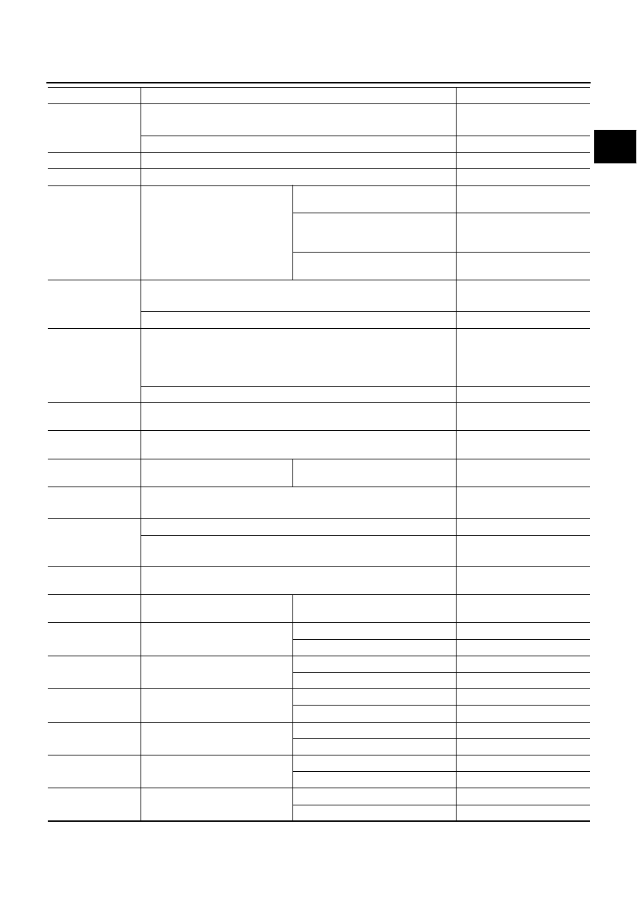
FUEL PUMP RLY
●
For 1 second after turning ignition switch ON
●
Engine running or cranking
ON
●
Except above conditions
OFF
VENT CONT/V
●
Ignition switch: ON
OFF
THRTL RELAY
●
Ignition switch: ON
ON
COOLING FAN
●
Engine: After warming up, idle
the engine
●
Air conditioner switch: OFF
Engine coolant temperature is 94
°
C
(201
°
F) or less
OFF
Engine coolant temperature is
between 95
°
C (203
°
F) and 99
°
C
(210
°
F)
LOW
Engine coolant temperature is 100
°
C
(212
°
F) or more
HI
HO2S1 HTR (B1)
HO2S1 HTR (B2)
●
Engine: After warming up
●
Engine speed: Below 3,600 rpm
ON
●
Engine speed: Above 3,600 rpm
OFF
HO2S2 HTR (B1)
HO2S2 HTR (B2)
●
Engine speed is below 3,600 rpm after the following conditions are met.
–
Engine: After warming up
–
Keeping the engine speed between 3,500 and 4,000 rpm for one minute
and at idle for one minute under no load
ON
●
Engine speed: Above 3,600 rpm
OFF
I/P PULLY SPD
●
Vehicle speed: More than 20 km/h (12 MPH)
Almost the same speed as the
tachometer indication
VEHICLE SPEED
●
Turn drive wheels and compare CONSULT-II value with the speedometer
indication.
Almost the same speed as the
speedometer indication
TRVL AFTER MIL
●
Ignition switch: ON
Vehicle has traveled after MIL has
turned ON.
0 - 65,535 km
(0 - 40,723 mile)
O2SEN HTR DTY
●
Engine coolant temperature when engine started: More than 80
°
C (176
°
F)
●
Engine speed: Below 3,600 rpm
Approx. 50%
AC PRESS SEN
●
Ignition switch: ON (Engine stopped)
Approx. 0V
●
Engine: Idle
●
Air conditioner switch: ON
1.0 - 4.0V
VEH SPEED SE
●
Turn drive wheels and compare CONSULT-II value with the speedometer
indication.
Almost the same speed as the
speedometer indication
SET VHCL SPD
●
Engine: Running
ASCD: Operating.
The preset vehicle speed is
displayed.
MAIN SW
●
Ignition switch: ON
CRUISE switch: Pressed
ON
CRUISE switch: Released
OFF
CANCEL SW
●
Ignition switch: ON
CANCEL switch: Pressed
ON
CANCEL switch: Released
OFF
RESUME/ACC SW
●
Ignition switch: ON
ACCEL/RES switch: Pressed
ON
ACCEL/RES switch: Released
OFF
SET SW
●
Ignition switch: ON
COAST/SET switch: Pressed
ON
COAST/SET switch: Released
OFF
BRAKE SW1
●
Ignition switch: ON
Brake pedal: Fully released
ON
Brake pedal: Slightly depressed
OFF
BRAKE SW2
●
Ignition switch: ON
Brake pedal: Fully released
OFF
Brake pedal: Slightly depressed
ON
MONITOR ITEM
CONDITION
SPECIFICATION