Nissan Murano Z50 (2003 year). Manual - part 86


  Index      Manuals     Nissan Murano Z50 (2003 year) - Service and Repair Manual


Search            copyright infringement  


Content      ..     84      85      86      87     ..


Nissan Murano Z50 (2003 year). Manual - part 86


TROUBLE DIAGNOSIS

EC-95

C

D

E

F

G

H

I

J

K

L

M

A

EC

Revision; 2004 April

2003 Murano

Fuel filler cap was left off or incorrectly screwed on, allowing fuel to evaporate into the atmosphere.
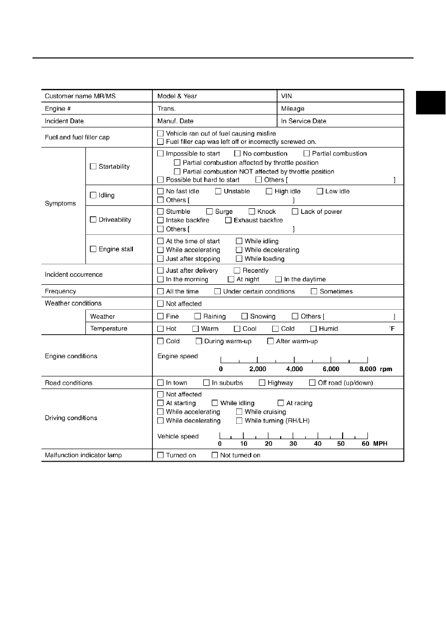
Worksheet Sample

MTBL0017

EC-96

TROUBLE DIAGNOSIS

Revision; 2004 April

2003 Murano

DTC Inspection Priority Chart

ABS004AT

If some DTCs are displayed at the same time, perform inspections one by one based on the following priority
chart.
NOTE:
If DTC U1000 and/or U1001 is displayed with other DTC, first perform the trouble diagnosis for DTC
U1000, U1001. Refer to 

EC-159

 .

Priority

Detected items (DTC)

1

U1000 U1001 CAN communication line

P0101 P0102 P0103 Mass air flow sensor

P0112 P0113 P0127 Intake air temperature sensor

P0117 P0118 P0125 Engine coolant temperature sensor

P0128 Thermostat function

P0122 P0123 P0222 P0223 P1225 P1226 P2135 Throttle position sensor

P0181 P0182 P0183 Fuel tank temperature sensor

P0327 P0328 Knock sensor

P0335 Crankshaft position sensor (POS)

P0340 P0345 Camshaft position sensor (PHASE)

P0460 P0461 P0462 P0463 Fuel level sensor

P0500 Vehicle speed sensor

P0605 ECM

P0705 Park/Neutral position (PNP) switch

P1229 Sensor power supply

P1610 - P1615 NATS

P1700 CVT control system

P1706 Park/Neutral position (PNP) switch

P2122 P2123 P2127 P2128 P2138 Accelerator pedal position sensor

TROUBLE DIAGNOSIS

EC-97

C

D

E

F

G

H

I

J

K

L

M

A

EC

Revision; 2004 April

2003 Murano

2

P0031P0032 P0051 P0052 Heated oxygen sensor 1 heater

P0037 P0038 P0057 P0058 Heated oxygen sensor 2 heater

P0132 P0133 P0134 P0152 P0153 P0154 P1143 P1144 P1163 P1164 Heated oxygen sensor 1

P0138 P0139 P0158 P0159 P1146 P1147 P1166 P1167 Heated oxygen sensor 2

P0441 EVAP control system purge flow monitoring

P0444 P0445 P1444 EVAP canister purge volume control solenoid valve

P0447 P1446 EVAP canister vent control valve

P0451 P0452 P0453 EVAP control system pressure sensor

P0550 Power steering pressure sensor

P0710 P0715 P0720 P0740 P0744 P0745 P0746 P0776 P0778 P0840 P0845 P1740 CVT related sensors, solenoid 
valves and switches

P1065 ECM power supply

P1111 P1136 Intake valve timing control solenoid valve

P1122 Electric throttle control function

P1124 P1126 P1128 Electric throttle control actuator

P1217 Engine over temperature (OVERHEAT)

P1720 Vehicle speed sensor

P1777 P1778 CVT step motor

P1805 Brake switch

3

P0011 P0021 Intake valve timing control

P0171 P0172 P0174 P0175 Fuel injection system function

P0300 - P0306 Misfire

P0420 P0430 Three way catalyst function

P0442 P0456 EVAP control system

P0506 P0507 Idle speed control system

P1121 Electric throttle control actuator

P1148 P1168 Closed loop control

P1211 TCS control unit

P1212 TCS communication line

P1564 ASCD steering switch

P1572 ASCD brake switch

P1574 ASCD vehicle speed sensor

P1715 Primary speed sensor

P1800 VIAS control solenoid valve

Priority

Detected items (DTC)

EC-98

TROUBLE DIAGNOSIS

Revision; 2004 April

2003 Murano

Fail-safe Chart

ABS004AU

When the DTC listed below is detected, the ECM enters fail-safe mode and the MIL lights up.

When there is an open circuit on MIL circuit, the ECM cannot warn the driver by lighting MIL up when
there is malfunction on engine control system.
Therefore, when electrical controlled throttle and part of ECM related diagnoses are continuously detected
as NG for 5 trips, ECM warns the driver that engine control system malfunctions and MIL circuit is open by
means of operating fail-safe function.
The fail-safe function also operates when above diagnoses except MIL circuit are detected and demands
the driver to repair the malfunction.

DTC No.

Detected items

Engine operating condition in fail-safe mode

P0102
P0103

Mass air flow sensor circuit

Engine speed will not rise more than 2,400 rpm due to the fuel cut.

P0117
P0118

Engine coolant tempera-
ture sensor circuit

Engine coolant temperature will be determined by ECM based on the time after turning 
ignition switch “ON” or “START”.
CONSULT-II displays the engine coolant temperature decided by ECM.

Condition

Engine coolant temperature decided 

(CONSULT-II display)

Just as ignition switch is turned 
ON or Start

40

°

C (104

°

F)

More than approx. 4 minutes after 
ignition ON or Start

80

°

C (176

°

F)

Except as shown above

40 - 80

°

C (104 - 176

°

F)

(Depends on the time)

When the fail-safe system for engine coolant temperature sensor is activated, the cooling 
fan operates while engine is running.

P0122
P0123
P0222
P0223
P2135

Throttle position sensor

The ECM controls the electric throttle control actuator in regulating the throttle opening in 
order for the idle position to be within +10 degrees.
The ECM regulates the opening speed of the throttle valve to be slower than the normal 
condition.
So, the acceleration will be poor. 

P1121

Electric throttle control 
actuator

(When electric throttle control actuator does not function properly due to the return spring 
malfunction:)
ECM controls the electric throttle actuator by regulating the throttle opening around the 
idle position. The engine speed will not rise more than 2,000 rpm.

(When throttle valve opening angle in fail-safe mode is not in specified range:)
ECM controls the electric throttle control actuator by regulating the throttle opening to 20 
degrees or less.

(When ECM detects the throttle valve is stuck open:)
While the vehicle is driving, it slows down gradually by fuel cut. After the vehicle stops, 
the engine stalls.
The engine can restart in N or P position, and engine speed will not exceed 1,000 rpm or 
more.

P1122

Electric throttle control 
function

ECM stops the electric throttle control actuator control, throttle valve is maintained at a 
fixed opening (approx. 5 degrees) by the return spring.

P1124
P1126

Throttle control motor relay

ECM stops the electric throttle control actuator control, throttle valve is maintained at a 
fixed opening (approx. 5 degrees) by the return spring.

P1128

Throttle control motor

ECM stops the electric throttle control actuator control, throttle valve is maintained at a 
fixed opening (approx. 5 degrees) by the return spring.

P1229

Sensor power supply

ECM stops the electric throttle control actuator control, throttle valve is maintained at a 
fixed opening (approx. 5 degrees) by the return spring.

P2122
P2123
P2127
P2128
P2138

Accelerator pedal position 
sensor

The ECM controls the electric throttle control actuator in regulating the throttle opening in 
order for the idle position to be within +10 degrees.
The ECM regulates the opening speed of the throttle valve to be slower than the normal 
condition.
So, the acceleration will be poor. 

Engine operating condition in fail-safe mode

Engine speed will not rise more than 2,500 rpm due to the fuel cut

TROUBLE DIAGNOSIS

EC-99

C

D

E

F

G

H

I

J

K

L

M

A

EC

Revision; 2004 April

2003 Murano

Basic Inspection

ABS004AV

1. 

INSPECTION START

1.

Check service records for any recent repairs that may indicate a related malfunction, or a current need for
scheduled maintenance.

2.

Open engine hood and check the following:

Harness connectors for improper connections

Wiring harness for improper connections, pinches and cut

Vacuum hoses for splits, kinks and improper connections

Hoses and ducts for leaks

Air cleaner clogging

Gasket

3.

Confirm that electrical or mechanical loads are not applied.

Headlamp switch is OFF.

Air conditioner switch is OFF.

Rear window defogger switch is OFF.

Steering wheel is in the straight-ahead position, etc.

4.

Start engine and warm it up until engine coolant temperature
indicator points the middle of gauge.
Ensure engine stays below 1,000 rpm.

5.

Run engine at about 2,000 rpm for about 2 minutes under no-
load.

6.

Make sure that no DTC is displayed with CONSULT-II or GST.

OK or NG

OK

>> GO TO 3.

NG

>> GO TO 2.

2. 

REPAIR OR REPLACE

Repair or replace components as necessary according to corresponding “Diagnostic Procedure”.

>> GO TO 3.

SEF983U

SEF976U

SEF977U

EC-100

TROUBLE DIAGNOSIS

Revision; 2004 April

2003 Murano

3. 

CHECK TARGET IDLE SPEED

 With CONSULT-II

1.

Run engine at about 2,000 rpm for about 2 minutes under no-load.

2.

Rev engine (2,000 to 3,000 rpm) two or three times under no-
load, then run engine at idle speed for about 1 minute.

3.

Read idle speed in “DATA MONITOR” mode with CONSULT-II.

 Without CONSULT-II

1.

Run engine at about 2,000 rpm for about 2 minutes under no-load.

2.

Rev engine (2,000 to 3,000 rpm) two or three times under no-load, then run engine at idle speed for about
1 minute.

3.

Check idle speed.

OK or NG

OK

>> GO TO 10.

NG

>> GO TO 4.

4. 

PERFORM ACCELERATOR PEDAL RELEASED POSITION LEARNING

1.

Stop engine.

2.

Perform 

EC-63, "Accelerator Pedal Released Position Learning"

 .

>> GO TO 5.

5. 

PERFORM THROTTLE VALVE CLOSED POSITION LEARNING

Perform 

EC-64, "Throttle Valve Closed Position Learning"

 .

>> GO TO 6.

SEF978U

CVT:

650 

±

 50 rpm (in "P" or "N" position)

SEF058Y

CVT:

650 

±

 50 rpm (in "P" or "N" position)

TROUBLE DIAGNOSIS

EC-101

C

D

E

F

G

H

I

J

K

L

M

A

EC

Revision; 2004 April

2003 Murano

6. 

PERFORM IDLE AIR VOLUME LEARNING

Refer to 

EC-64, "Idle Air Volume Learning"

 .

Is Idle Air Volume Learning carried out successfully?

Yes or No

Yes

>> GO TO 7.

No

>> 1. Follow the instruction of “Idle Air Volume Learning”.

2. GO TO 4.

7. 

CHECK TARGET IDLE SPEED AGAIN

 With CONSULT-II

1.

Start engine and warm it up to normal operating temperature.

2.

Read idle speed in “DATA MONITOR” mode with CONSULT-II.

 Without CONSULT-II

1.

Start engine and warm it up to normal operating temperature.

2.

Check idle speed.

OK or NG

OK

>> GO TO 10.

NG

>> GO TO 8.

8. 

DETECT MALFUNCTIONING PART

Check the following.

Check camshaft position sensor (PHASE) and circuit. Refer to 

EC-328

 .

Check crankshaft position sensor (POS) and circuit. Refer to 

EC-322

 .

OK or NG

OK

>> GO TO 9.

NG

>> 1. Repair or replace.

2. GO TO 4.

9. 

CHECK ECM FUNCTION 

1.

Substitute another known-good ECM to check ECM function. (ECM may be the cause of an incident, but
this is the rarely the case.)

2.

Perform initialization of NVIS (NATS) system and registration of NVIS (NATS) ignition key IDs. Refer to

EC-83, "NVIS (Nissan Vehicle Immobilizer System — NATS)"

 .

>> GO TO 4.

10. 

CHECK IGNITION TIMING

1.

Run engine at idle.

2.

Check ignition timing with a timing light.

OK or NG

OK

>> INSPECTION END

NG

>> GO TO 11.

CVT:

650 

±

 50 rpm (in "P" or "N" position)

CVT:

650 

±

 50 rpm (in "P" or "N" position)

CVT:

15 

±

 5

°

 BTDC (in "P" or "N" position)

EC-102

TROUBLE DIAGNOSIS

Revision; 2004 April

2003 Murano

11. 

PERFORM ACCELERATOR PEDAL RELEASED POSITION LEARNING

1.

Stop engine.

2.

Perform 

EC-63, "Accelerator Pedal Released Position Learning"

 .

>> GO TO 12.

12. 

PERFORM THROTTLE VALVE CLOSED POSITION LEARNING

Perform 

EC-64, "Throttle Valve Closed Position Learning"

 .

>> GO TO 13.

13. 

PERFORM IDLE AIR VOLUME LEARNING

Refer to 

EC-64, "Idle Air Volume Learning"

 .

Is Idle Air Volume Learning carried out successfully?

Yes or No

Yes

>> GO TO 14.

No

>> 1. Follow the instruction of “Idle Air Volume Learning”.

2. GO TO 4.

14. 

CHECK TARGET IDLE SPEED AGAIN

 With CONSULT-II

1.

Start engine and warm it up to normal operating temperature.

2.

Read idle speed in “DATA MONITOR” mode with CONSULT-II.

 Without CONSULT-II

1.

Start engine and warm it up to normal operating temperature.

2.

Check idle speed.

OK or NG

OK

>> GO TO 15.

NG

>> GO TO 17.

15. 

CHECK IGNITION TIMING AGAIN

1.

Run engine at idle.

2.

Check ignition timing with a timing light.

OK or NG

OK

>> INSPECTION END

NG

>> GO TO 16.

16. 

CHECK TIMING CHAIN INSTALLATION

Check timing chain installation. Refer to 

EM-54, "TIMING CHAIN"

 .

OK or NG

OK

>> GO TO 17.

NG

>> 1. Repair the timing chain installation.

2. GO TO 4.

CVT:

650 

±

 50 rpm (in "P" or "N" position)

CVT:

650 

±

 50 rpm (in "P" or "N" position)

CVT:

15 

±

 5

°

 BTDC (in "P" or "N" position)

TROUBLE DIAGNOSIS

EC-103

C

D

E

F

G

H

I

J

K

L

M

A

EC

Revision; 2004 April

2003 Murano

17. 

DETECT MALFUNCTIONING PART

Check the following.

Check camshaft position sensor (PHASE) and circuit. Refer to 

EC-328

 .

Check crankshaft position sensor (POS) and circuit. Refer to 

EC-322

 .

OK or NG

OK

>> GO TO 18.

NG

>> 1. Repair or replace.

2. GO TO 4.

18. 

CHECK ECM FUNCTION 

1.

Substitute another known-good ECM to check ECM function. (ECM may be the cause of an incident, but
this is the rarely the case.)

2.

Perform initialization of NVIS (NATS) system and registration of NVIS (NATS) ignition key IDs. Refer to

EC-83, "NVIS (Nissan Vehicle Immobilizer System — NATS)"

 .

>> GO TO 4.

Symptom Matrix Chart

ABS004AW

SYSTEM — BASIC ENGINE CONTROL SYSTEM

SYMPTOM

Reference 
page

HARD/

NO ST

AR

T

/REST

AR

T (

EXCP

HA)

ENGI

NE ST

ALL

HESI

T

A

TION/

SURGING/

FL

A

T

 SPOT

SP

ARK KNOCK/DET

ONA

T

IO

N

L

A

CK OF 

POW

ER/

P

O

OR ACCEL

ERA

TION

HI

GH I

D

L

E

/L

OW

 I

D

L

E

RO

UGH IDL

E/

HUNTING

ID

LING VI

BRA

TION

SL

OW

/NO RETURN 

T

O

 I

D

L

E

OVERHEA

TS/

W

A

TER TEMPERA

TURE HI

GH

EXCESSIVE FUEL

 CONSUMP

T

IO

N

EXCESSIVE OIL 

CONSUM

P

T

ION

BA

TTER

DEAD (

UNDER CHARGE)

Warranty symptom code

AA

AB

AC

AD

AE

AF

AG

AH

AJ

AK

AL

AM

HA

Fuel

Fuel  pump  circuit

1

1

2

3

2

2

2

3

2

EC-623

Fuel pressure regulator system

3

3

4

4

4

4

4

4

4

4

EC-66

Injector  circuit

1

1

2

3

2

2

2

2

EC-617

Evaporative emission system

3

3

4

4

4

4

4

4

4

4

EC-652

Air

Positive crankcase ventilation sys-
tem

3

3

4

4

4

4

4

4

4

4

1

EC-664

Incorrect idle speed adjustment

1

1

1

1

1

EC-53

Electric  throttle  control  actuator

1

1

2

3

3

2

2

2

2

2

2

EC-436

EC-438

Ignition

Incorrect  ignition  timing  adjustment

3

3

1

1

1

1

1

1

EC-53

Ignition  circuit

1

1

2

2

2

2

2

2

EC-596

Main power supply and ground circuit

2

2

3

3

3

3

3

2

3

EC-152

EC-104

TROUBLE DIAGNOSIS

Revision; 2004 April

2003 Murano

1 - 6: The numbers refer to the order of inspection.
(continued on next page)

Mass air flow sensor circuit

1

1

2

2

2

2

2

2

EC-183

EC-191

Engine coolant temperature sensor circuit

3

3

3

EC-203

EC-215

Heated oxygen sensor 1 circuit

EC-223

EC-233

 , 

EC-246

 , 

EC-454

 , 

EC-460

Throttle position sensor circuit

2

2

EC-208

EC-304

 , 

EC-508

 , 

EC-510

 , 

EC-512

 , 

EC-582

Accelerator pedal position sensor circuit

3

2

1

EC-569

EC-575

 , 

EC-589

Knock sensor circuit

2

3

EC-317

Crankshaft position sensor (POS) circuit

2

2

EC-322

Camshaft position sensor (PHASE) circuit

3

2

EC-328

Vehicle speed signal circuit

2

3

3

3

EC-411

Power steering pressure sensor circuit

2

3

3

EC-417

ECM

2

2

3

3

3

3

3

3

3

3

3

EC-422

EC-425

Intake valve timing control solenoid valve cir-
cuit

3

2

1

3

2

2

3

3

EC-429

PNP switch circuit

3

3

3

3

3

EC-550

VIAS control solenoid valve circuit

1

EC-559

Refrigerant pressure sensor circuit

2

3

3

4

EC-634

Electrical load signal circuit

3

EC-639

Air  conditioner  circuit

2

2

3

3

3

3

3

3

3

3

2

ATC-55

VDC/TCS/ABS control unit
ABS actuator and electric unit (control unit)

4

BRC-98

 or 

BRC-31

SYMPTOM

Reference 
page

HARD/

NO ST

AR

T

/REST

AR

T (

EXCP

. H

A

)

ENGI

NE ST

ALL

HESI

T

A

TION/

SURGING/

FL

A

T

 SPOT

SP

ARK KNOCK/DET

ONA

T

IO

N

L

A

CK OF 

POW

ER/POO

R ACCEL

ERA

TION

HI

GH I

D

L

E

/L

OW

 I

D

L

E

ROUG

H IDL

E/

HUNTING

ID

L

ING VI

BRA

TION

SL

OW

/N

O RETURN 

T

O

 I

D

L

E

OVERHEA

TS/

W

A

TER TEMPERA

TURE HI

GH

EXCESSIVE F

U

E

L

 CONSUMP

T

IO

N

EXCESSIVE OIL 

CONSUM

P

T

ION

BA

TTER

DEAD (

UNDER CHARGE)

Warranty symptom code

AA

AB

AC

AD

AE

AF

AG

AH

AJ

AK

AL

AM

HA

TROUBLE DIAGNOSIS

EC-105

C

D

E

F

G

H

I

J

K

L

M

A

EC

Revision; 2004 April

2003 Murano

SYSTEM — ENGINE MECHANICAL & OTHER

SYMPTOM

Reference 
page

HARD/

NO ST

AR

T/

REST

AR

T (

E

X

C

P

. HA)

ENGI

NE ST

ALL

HESIT

A

TION/SURG

ING/FL

A

T

 S

P

OT

SP

ARK K

N

O

C

K/DET

ONA

T

IO

N

L

A

CK 

OF P

O

W

E

R/POOR ACCEL

E

R

A

TION

HI

GH ID

L

E

/L

OW

 I

D

L

E

ROUGH IDL

E/HUNTI

NG

ID

L

ING VI

B

R

A

T

ION

SL

OW

/N

O RETURN 

T

O

 I

D

L

E

OVERHEA

TS/W

A

T

ER TEMPERA

TURE 

HI

GH

EXCESSIVE FUEL CO

NSUMP

T

ION

EXCESSIVE O

IL CONSUMP

T

IO

N

BA

TTER

Y DEA

D (UNDER CHARGE)

Warranty symptom code

AA

AB

AC

AD

AE

AF

AG

AH

AJ

AK

AL

AM

HA

Fuel

Fuel tank

5

5

FL-9

Fuel piping

5

5

5

5

5

5

EM-38

Vapor lock

Valve deposit

5

5

5

5

5

5

5

Poor fuel (Heavy weight gaso-
line, Low octane)

Air

Air duct

5

5

5

5

5

5

EM-14

Air cleaner

EM-14

Air leakage from air duct
(Mass air flow sensor — electric 
throttle control actuator)

5

5

5

5

EM-14

Electric throttle control actuator

EM-16

Air leakage from intake manifold/
Collector/Gasket

EM-16

EM-20

Cranking

Battery

1

1

1

1

1

1

1

1

SC-4

Generator circuit

SC-18

Starter circuit

3

SC-10

Signal plate

6

EM-100

PNP switch

4

CVT-85

Engine

Cylinder head

5

5

5

5

5

5

5

5

EM-84

Cylinder head gasket

4

3

Cylinder block

6

6

6

6

6

6

6

6

4

EM-100

Piston

Piston ring

Connecting rod

Bearing

Crankshaft

Valve 
mecha-
nism

Timing chain

5

5

5

5

5

5

5

5

EM-54

Camshaft

EM-70

Intake valve timing control

EM-54

Intake valve

3

EM-84

Exhaust valve

EC-106

TROUBLE DIAGNOSIS

Revision; 2004 April

2003 Murano

1 - 6: The numbers refer to the order of inspection.

Exhaust

Exhaust manifold/Tube/Muffler/
Gasket

5

5

5

5

5

5

5

5

EM-22

EX-

3

Three way catalyst

Lubrica-
tion

Oil pan/Oil strainer/Oil pump/Oil 
filter/Oil gallery/Oil cooler

5

5

5

5

5

5

5

5

EM-26

LU-

12

 , 

LU-9

 , 

LU-10

Oil level (Low)/Filthy oil

LU-6

Cooling

Radiator/Hose/Radiator filler cap

5

5

5

5

5

5

5

4

5

CO-12

CO-16

Thermostat

5

CO-24

Water pump

CO-20

Water gallery

CO-26

Coolant level (Low)/Contami-
nated coolant

5

CO-8

NVIS (NISSAN Vehicle Immobilizer System — 
NATS)

1

1

EC-83

 or 

BL-187

SYMPTOM

Reference 
page

HARD/

NO ST

AR

T

/REST

AR

T (

EXCP

. H

A

)

ENGI

NE ST

ALL

HESI

T

A

TION/

SURGING/

FL

A

T

 SPOT

SP

ARK KNOCK/DET

ONA

T

IO

N

L

A

CK OF 

POW

ER/POO

R ACCEL

ERA

TION

HI

GH I

D

L

E

/L

OW

 I

D

L

E

ROUG

H IDL

E/

HUNTING

ID

L

ING VI

BRA

TION

SL

OW

/N

O RETURN 

T

O

 I

D

L

E

OVERHEA

TS/

W

A

TER TEMPERA

TURE HI

GH

EXCESSIVE F

U

E

L

 CONSUMP

T

IO

N

EXCESSIVE OIL 

CONSUM

P

T

ION

BA

TTER

DEAD (

UNDER CHARGE)

Warranty symptom code

AA

AB

AC

AD

AE

AF

AG

AH

AJ

AK

AL

AM

HA

TROUBLE DIAGNOSIS

EC-107

C

D

E

F

G

H

I

J

K

L

M

A

EC

Revision; 2004 April

2003 Murano

Engine Control Component Parts Location

ABS004AX

PBIB1289E

EC-108

TROUBLE DIAGNOSIS

Revision; 2004 April

2003 Murano

PBIB1290E

TROUBLE DIAGNOSIS

EC-109

C

D

E

F

G

H

I

J

K

L

M

A

EC

Revision; 2004 April

2003 Murano

PBIB1291E

EC-110

TROUBLE DIAGNOSIS

Revision; 2004 April

2003 Murano

PBIB1292E


Content      ..     84      85      86      87     ..