Nissan Murano Z50 (2003 year). Manual - part 85
ON BOARD DIAGNOSTIC (OBD) SYSTEM
EC-79
C
D
E
F
G
H
I
J
K
L
M
A
EC
Revision; 2004 April
2003 Murano
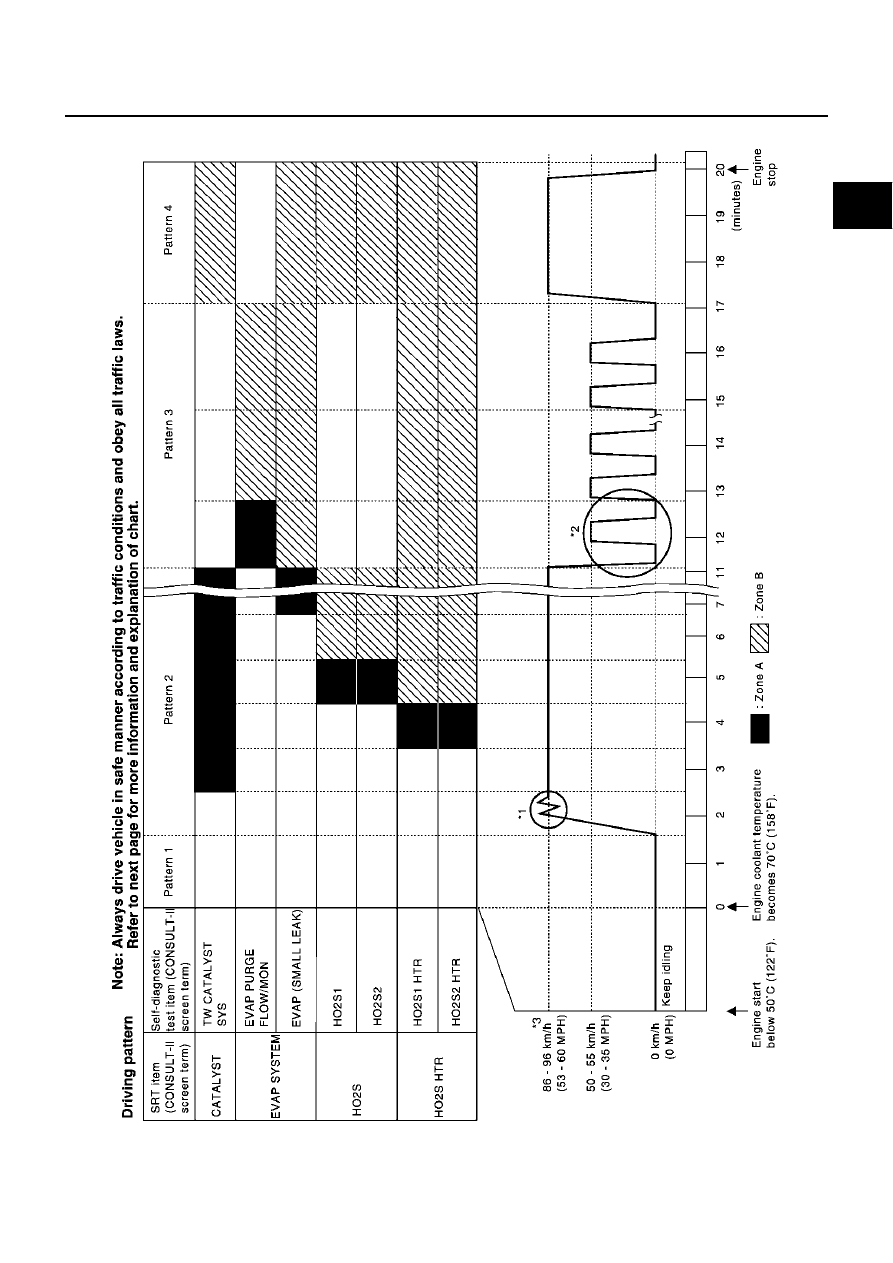
Driving Pattern
PBIB1053E
|
|
|
ON BOARD DIAGNOSTIC (OBD) SYSTEM EC-79 C D E F G H I J K L M A EC Revision; 2004 April 2003 Murano Driving Pattern PBIB1053E |