Nissan Murano Z50 (2003 year). Manual - part 79
WARNING CHIME
DI-97
C
D
E
F
G
H
I
J
L
M
A
B
DI
Revision; 2004 April
2003 Murano
●
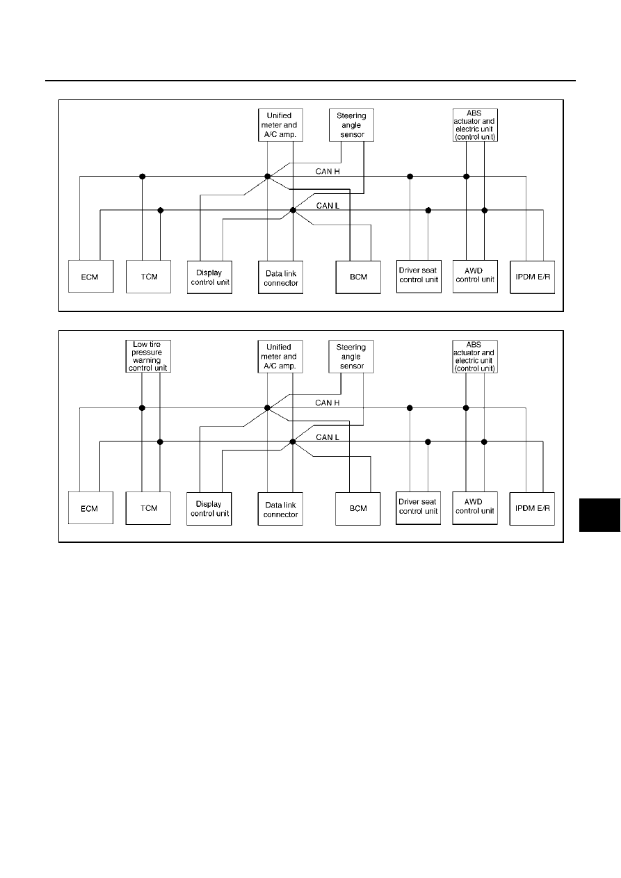
Type31
●
Type32
SKIA4932E
SKIA4933E
|
|
|
WARNING CHIME DI-97 C D E F G H I J L M A B DI Revision; 2004 April 2003 Murano ● Type31 ● Type32 SKIA4932E SKIA4933E |