Nissan Murano Z50 (2003 year). Manual - part 61
CVT SYSTEM
CVT-17
D
E
F
G
H
I
J
K
L
M
A
B
CVT
Revision; 2004 April
2003 Murano
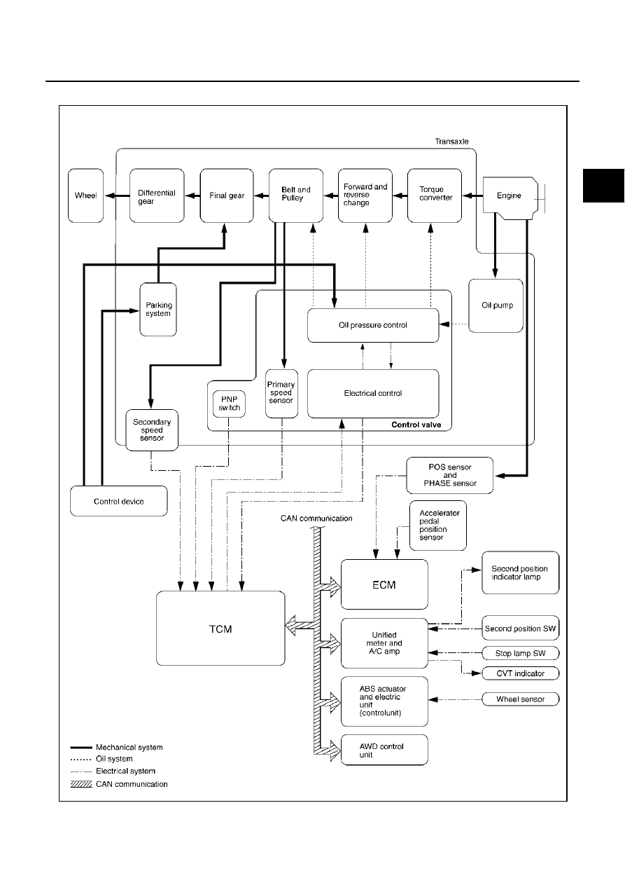
Control System
ACS0029J
SCIA1929E
|
|
|
CVT SYSTEM CVT-17 D E F G H I J K L M A B CVT Revision; 2004 April 2003 Murano Control System ACS0029J SCIA1929E |