Nissan Murano Z50 (2003 year). Manual - part 57


  Index      Manuals     Nissan Murano Z50 (2003 year) - Service and Repair Manual


Search            copyright infringement  


Content      ..     55      56      57      58     ..


Nissan Murano Z50 (2003 year). Manual - part 57


TROUBLE DIAGNOSIS

BRC-133

[VDC/TCS/ABS]

C

D

E

G

H

I

J

K

L

M

A

B

BRC

Revision; 2004 April

2003 Murano

3. 

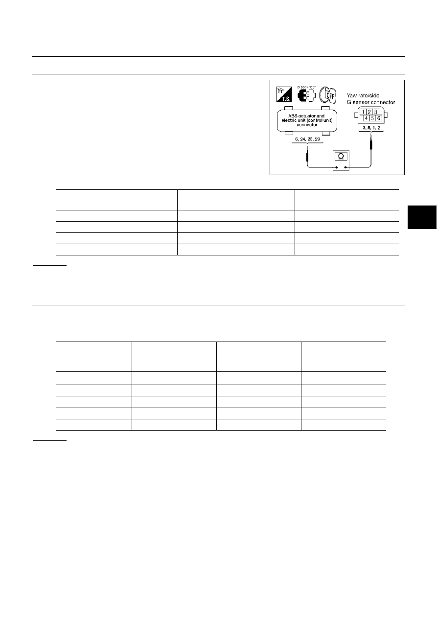
CHECK YAW RATE SENSOR/SIDE G SENSOR HARNESS

1.

Turn ignition switch OFF and disconnect yaw rate/side/decel G
sensor connector M61 and ABS actuator and electric unit (con-
trol unit) connector E24.

2.

Check continuity between ABS actuator and electric unit (control
unit) vehicle side connector and yaw rate/side/decel G sensor
vehicle side connector.

OK or NG

OK

>> GO TO 4.

NG

>> If open or short in harness, repair or replace harness.

4. 

CHECK YAW RATE SENSOR/SIDE/DECEL G SENSOR

1.

Connect yaw rate /side/decel G sensor M61 and ABS actuator and electric unit (control unit) connector
E24.

2.

Use “Data Monitor” to check if yaw rate sensor/side/decel G sensor are normal. 

OK or NG

OK

>> Perform ABS actuator and electric unit (control unit) self diagnosis again.

NG

>> Replace the malfunctioning yaw rate sensor/side/decel G sensor, and then re-conduct ABS actu-

ator and electric unit (control unit) self-diagnosis.

PFIA0460E

ABS actuator and electric unit 

(control unit)

Yaw rate/side/decel G sensor

Continuity 

6 (G/R)

3 (G/R)

Yes

24 (P/L)

5 (P/L)

Yes

25 (W)

1 (W/G)

Yes

29 (R)

2 (R/Y)

Yes

Vehicle status

Yaw rate sensor

(Data monitor stan-

dard)

Side G sensor

(Data monitor stan-

dard)

Decel G sensor

(Data monitor stan-

dard)

When stopped

–4 to +4deg/s

–1.1 to +1.1 m/s

2

–0.11 G to +0.11 G

Right turn

Negative value

Negative value

Left turn

Positive value

Positive value

Speed up

Negative value

Speed down

Positive value

BRC-134

[VDC/TCS/ABS]

TROUBLE DIAGNOSIS

Revision; 2004 April

2003 Murano

Inspection 7 Solenoid and VDC Change-Over Valve System

AFS0020A

INSPECTION PROCEDURE

1. 

CHECK SELF-DIAGNOSIS RESULT

Check self-diagnosis results.

Is above displayed in self-diagnosis display items?

YES

>> GO TO 2.

NO

>> Inspection END

2. 

CHECK CONNECTOR

1.

Disconnect ABS actuator and electric unit (control unit) connector E24 check terminals for deformation,
disconnection, looseness, and so on. If there is an error, repair or replace terminal.

2.

Securely reconnect connectors and conduct self-diagnosis.

OK or NG

OK

>> Connector terminal contact is loose, damaged, open or shorted.

NG

>> GO TO 3.

Self-diagnosis results

FR LH IN SOL

FR LH OUT SOL

RR RH IN SOL 

RR RH OUT SOL 

FR RH IN SOL

FR RH OUT SOL

RR LH IN SOL

RR LH OUT SOL

CV 1

CV 2

SV 1

SV 2

TROUBLE DIAGNOSIS

BRC-135

[VDC/TCS/ABS]

C

D

E

G

H

I

J

K

L

M

A

B

BRC

Revision; 2004 April

2003 Murano

3. 

CHECK SOLENOID POWER AND GROUND CIRCUIT

1.

Disconnect ABS actuator and electric unit (control unit) connector E24.

2.

Check voltage between ABS actuator and electric unit (control
unit) harness connector E24 and ground.

3.

Check resistance between ABS actuator and electric unit (con-
trol unit) harness connector E24 and ground.

OK or NG

OK

>> Perform self-diagnosis again. If the same results

appear, replace ABS actuator and electric unit (control
unit). Refer to 

BRC-148, "ACTUATOR AND ELECTRIC

UNIT (ASSEMBLY)"

 .

NG

>> Repair harness or connectors.

Inspection 8 Actuator Motor, Motor Relay, and Circuit

AFS0020B

INSPECTION PROCEDURE 

1. 

CHECK SELF-DIAGNOSIS RESULTS (1)

Check self-diagnosis results.

Is above displayed in self-diagnosis display items?

YES

>> GO TO 2.

NO

>> Inspection END.

2. 

CHECK SELF-DIAGNOSIS RESULTS (2)

1.

Disconnect ABS actuator and electric unit (control unit) connector E24. Then reconnect it securely.

2.

Perform self-diagnosis again.

Do any self-diagnosis items appear?

YES

>> GO TO 3.

NO

>> Repair or replace the applicable connector.

ABS actuator and electric 

unit (control unit)

Ground

Voltage (V)

(Approx.)

32 (R/B)

12 V

LFIA0148E

ABS actuator and electric 

unit (control unit)

Ground

Resistance 

(

)

(Approx.)

16 (B), 47 (B)

LFIA0152E

Self-diagnosis results

CONSULT-II display items

PUMP MOTOR

ACTUATOR RLY

BRC-136

[VDC/TCS/ABS]

TROUBLE DIAGNOSIS

Revision; 2004 April

2003 Murano

3. 

CHECK ABS MOTOR AND MOTOR RELAY POWER SYSTEM

1.

Disconnect ABS actuator and electric unit (control unit) connector E24.

2.

Check voltage between ABS actuator and electric unit (control
unit) connector E24 and ground.

3.

Check resistance between ABS actuator and electric unit (con-
trol unit) connector E24 and ground.

OK or NG

OK

>> Perform self-diagnosis again. If the same result

appears, replace ABS actuator and electric unit (control
unit). Refer to 

BRC-148, "ACTUATOR AND ELECTRIC

UNIT (ASSEMBLY)"

 .

NG

>> Repair harness or connectors.

Inspection 9 ABS Actuator and Electric Unit (Control Unit) Power Supply and 
Ground Circuit

AFS0020C

INSPECTION PROCEDURE

1. 

CHECK SELF-DIAGNOSIS RESULT 

Check self-diagnosis results.

Does “BATTERY VOLTAGE” appear in self-diagnosis results display?

YES

>> GO TO 2.

NO

>> Inspection END.

2. 

CHECK STARTING

1.

Disconnect ABS actuator and electric unit (control unit) connector E24. Then reconnect it securely.

2.

Perform self-diagnosis.

Do any self-diagnosis items appear?

YES

>> GO TO 3.

NO

>> Repair or replace connector.

ABS actuator and electric 

unit (control unit)

Ground

Voltage (V)

(Approx.)

1 (G/R)

12 V

LFIA0149E

ABS actuator and electric 

unit (control unit)

Ground

Resistance 

(

)

(Approx.)

16 (B)

LFIA0147E

Self-diagnosis results

CONSULT-II display items

BATTERY VOLTAGE

TROUBLE DIAGNOSIS

BRC-137

[VDC/TCS/ABS]

C

D

E

G

H

I

J

K

L

M

A

B

BRC

Revision; 2004 April

2003 Murano

3. 

CHECK ABS ACTUATOR AND ELECTRIC UNIT (CONTROL UNIT) POWER SUPPLY

1.

Disconnect ABS actuator and electric unit (control unit) connector E24.

2.

Turn ignition switch ON (but do not start engine). Check voltage
between ABS actuator and electric unit (control unit) harness
connector E24 and ground.

OK or NG

OK

>> GO TO 4.

NG

>> GO TO 5

4. 

CHECK ABS ACTUATOR AND ELECTRIC UNIT (CONTROL UNIT) GROUND CIRCUITS

Check ABS actuator and electric unit (control unit) ground circuits.

OK or NG

OK

>> Perform ABS actuator and electric unit (control unit) self-

diagnosis again.

NG

>> Repair harness or connectors.

5. 

CHECK ABS ACTUATOR AND ELECTRIC UNIT (CONTROL UNIT) POWER SYSTEM

1.

Disconnect ABS actuator and electric unit (control unit) connector E24. 

2.

Check continuity between battery positive terminal and ABS
actuator and electric unit (control unit) connector E24.

OK or NG

YES

>> Check for malfunction conditions in battery (terminal

looseness, low voltage, etc.) and alternator.

NO

>> Repair harness or connectors.

Inspection 10 Stop Lamp Switch System

AFS0020D

INSPECTION PROCEDURE

1. 

CHECK SELF-DIAGNOSIS RESULT

Check self-diagnosis results.

Is above displayed in self-diagnosis display items?

YES

>> GO TO 2.

NO

>> Inspection END

ABS actuator and electric 

unit (control unit)

Ground

Voltage (V)

(Approx.)

4 (GR)

12 V

LFIA0151E

ABS actuator and electric 

unit (control unit)

Ground

Continuity

16 (B), 47 (B)

Yes

LFIA0152E

ABS actuator and electric 

unit (control unit)

Battery 

positive 

terminal

Continuity

4 (G/R)

Yes

PFIA0461E

Self-diagnosis results

STOP LAMP SW

BRC-138

[VDC/TCS/ABS]

TROUBLE DIAGNOSIS

Revision; 2004 April

2003 Murano

2. 

CHECK CONNECTOR

1.

Disconnect the stop lamp switch connector E116 and ABS actuator and electric unit (control unit) connec-
tor E24 and check terminals for deformation, disconnection, looseness, and so on. If any malfunction is
found, repair or replace terminal.

2.

Securely reconnect connectors.

3.

Start engine.

4.

Repeat pumping brake pedal carefully several times, then perform self-diagnosis again.

OK or NG

OK

>> Connector terminal contact is loose, damaged, open or shorted.

NG

>> GO TO 3.

3. 

CHECK STOP LAMP SWITCH CIRCUIT

1.

Turn ignition switch OFF and disconnect stop lamp switch con-
nector E116 and ABS actuator and electric unit (control unit)
connector E24.

2.

Check continuity between stop lamp switch harness connector
E116 and ABS actuator and electric unit (control unit) harness
connector E24. 

OK or NG

OK

>> Connect connectors and conduct a ABS actuator and electric unit (control unit) self-diagnosis.

NG

>> Open or short in harness. Repair or replace harness.

Inspection 11 Brake Fluid Level Sensor System

AFS0020E

INSPECTION PROCEDURE

1. 

CHECK SELF-DIAGNOSIS RESULT

1.

Check the brake reservoir tank fluid level. If the level is low, add brake fluid.

2.

Erase self-diagnosis results and check self-diagnosis results.

Is above displayed in self-diagnosis display items?

YES

>> GO TO 2.

NO

>> Inspection END

2. 

CHECK CONNECTOR

1.

Disconnect the brake fluid level sensor connector E21 and ABS actuator and electric unit (control unit)
connector E24 and check terminal for deformation, disconnection, looseness, and so on. If there is any
malfunction condition, repair or replace terminal.

2.

Securely reconnect connectors and Re-conduct self-diagnosis.

OK or NG

OK

>> Connector terminal contact is loose, damaged, open or shorted.

NG

>> GO TO 3.

ABS actuator and electric 

unit (control unit)

Stop lamp 

switch 

Continuity

41 (R/G)

2 (R/G)

Yes

LFIA0150E

Self-diagnosis results

BR FLUID LEVEL LOW

TROUBLE DIAGNOSIS

BRC-139

[VDC/TCS/ABS]

C

D

E

G

H

I

J

K

L

M

A

B

BRC

Revision; 2004 April

2003 Murano

3. 

CHECK HARNESS BETWEEN THE BRAKE FLUID LEVEL SENSOR AND ABS ACTUATOR AND 

ELECTRIC UNIT (CONTROL UNIT)

1.

Turn ignition switch OFF and disconnect the brake fluid level
sensor connector E21, ABS actuator and electric unit (control
unit) connectors E24.

2.

Check continuity between the brake fluid level sensor connector
E21 and ABS actuator and electric unit (control unit) connector
E24 and ground.

OK or NG

OK

>> Connect connectors and conduct a ABS actuator and electric unit (control unit) self-diagnosis.

NG

>> If the open or short in harness, repair or replace harness.

Inspection 12 When “ST ANG SEN SIGNAL” Appears on Self-Diagnosis Results 
Display

AFS0020F

INSPECTION PROCEDURE

1. 

CHECK SELF DIAGNOSIS RESULTS (1)

Check self-diagnosis results.

Dose anything besides “ST ANG SEN SIGNAL” appear on self-diagnosis results display?

YES

>> Inspect and repair the indicated items. Then perform self-diagnosis again.

NO

>> Perform adjustment of steering angle sensor neutral position. Then GO TO 2

2. 

CHECK SELF DIAGNOSIS RESULTS (2)

Turin ignition switch OFF, and ON to erase self-diagnosis results, and perform ABS actuator and electric unit
(control unit) self-diagnosis again.

Dose anything appear on self-diagnosis results display?

YES

>> Replace steering angle sensor. Then perform adjustment of neutral position and perform self-

diagnosis again.

NO

>> Inspection END.

Inspection 13 CAN Communication System

AFS002QT

INSPECTION PROCEDURE

1. 

CHECK CONNECTOR

1.

Turn ignition switch OFF, disconnect the ABS actuator and electric unit (control unit) connector E24, and
check the terminal for deformation, disconnection, looseness, and so on. If there is a malfunction, repair
or replace the terminal.

2.

Reconnect connector to perform self-diagnosis.

Is “CAN COMM CIRCUIT” or “ST ANG SEN COM CIR” displayed in the self-diagnosis display items?

YES

>> Print out the self-diagnostic results, and refer to 

LAN-10, "Precautions When Using CONSULT-II"

 .

NO

>> Connector terminal connection is loose, damaged, open, or shorted.

ABS actuator and elec-

tric unit (control unit)

Brake fluid level sensor

Continuity

8 (SB)

1 (SB)

Yes

8 (SB)

Ground

No

Ground

2 (B)

Yes

PFIA0433E

Self-diagnosis results

ST ANG SEN SIGNAL

BRC-140

[VDC/TCS/ABS]

TROUBLE DIAGNOSIS

Revision; 2004 April

2003 Murano

Inspection 14 When “DECEL G SEN SET” Appears on Self-Diagnosis Results 
Display

AFS0020H

INSPECTION PROCEDURE

1. 

CHECK SELF DIAGNOSIS RESULTS (1)

Check self-diagnosis results.

Dose anything besides “DECEL G SEN SET” appear on self-diagnosis results display?

YES

>> Inspect and repair the indicated items. Then perform self-diagnosis again.

NO

>> Perform adjustment of Decel G Sensor neutral position. Then GO TO 2.

2. 

CHECK SELF-DIAGNOSIS RESULTS (2)

Turn ignition switch OFF, and ON to erase self-diagnosis results, and perform ABS actuator and electric unit
(control unit) self-diagnosis again.
Dose anything appear on self-diagnosis results display?

YES

>> Replace Yaw rate/side/decel G sensor. Then perform adjustments of neutral position and perform

self-diagnosis again.

NO

>> Inspection END.

Inspection 15 When “ESTM VEH SPD SIG” Appears on Self-Diagnosis Results 
Display

AFS0020I

INSPECTION PROCEDURE

1. 

CHECK SELF DIAGNOSIS RESULTS

Conduct an CVT self-diagnosis results.

Dose anything besides “ESTM VEH SPD SIG” appear on self-diagnosis results display?

YES

>> Inspect and repair the indicated items. Then perform self-diagnosis again.

NO

>>

Erase CVT self-diagnosis. The inspection is complete.

NOTE:
If there is no error about ABS actuator and electric unit (control unit), “ESTM VHE SPD SIG”
may be displayed in CVT self-diagnosis depending no the timing of cranking.

Inspection 16 VDC OFF Indicator Lamp Dose Not Illuminate

AFS0020J

INSPECTION PROCEDURE

1. 

CHECK VDC OFF INDICATOR LAMP

Disconnect ABS actuator and electric unit (control unit) connector E24.

Do ABS warning lamp and VDC OFF indicator lamp illuminate?

OK

>> Malfunction in combination meter system. Inspect combination meter.

NG

>> Malfunction of ABS actuator and electric unit (control unit). Repair or replace control unit.

Self-diagnosis results

DECEL G SEN SET

Self-diagnosis results

ESTM VEH SPD SIG

TROUBLE DIAGNOSIS

BRC-141

[VDC/TCS/ABS]

C

D

E

G

H

I

J

K

L

M

A

B

BRC

Revision; 2004 April

2003 Murano

Component Inspection

AFS0020K

VDC OFF SWITCH

Turn ignition switch OFF, and disconnect the VDC OFF switch
connector M17, and check continuity between terminals 1 and 2.

Symptom 1 Excessive ABS Function Operation Frequency

AFS0020L

1. 

CHECK WHEEL SENSOR

Wheel Sensor Inspection

Sensor mount and damage inspection

Sensor rotor mount and damage inspection

Sensor connector connection inspection

Sensor harness inspection

OK or NG

OK

>> GO TO 2.

NG

>> Sensor or sensor rotor replacement

2. 

CHECK FRONT AND REAR AXLE

Make sure there is no excessive play in front and rear axles.
OK or NG

OK

>> GO TO 3.

NG

>> Repair.

3. 

CHECK ABS WARNING LAMP DISPLAY

Make sure ABS warning lamp turns OFF approximately 2 sec. After ignition switch is turned on or when driv-
ing.
OK or NG

OK

>> Normal

NG

>> Perform self-diagnosis. Refer to 

BRC-114, "SELF-DIAGNOSIS"

 .

Symptom 2 Unexpected Pedal Reaction

AFS0020M

1. 

CHECK BRAKE PEDAL STROKE

Check brake pedal stroke.

Is the stroke too long?

YES

>>

Bleed air from the brake piping.

Check the brake pedal, brake booster, and master cylinder mount for play, looseness, and
brake system for fluid leaks, etc. If any malfunctions are found, make repair.

NO

>> GO TO 2.

2. 

CHECK PEDAL FORCE

Check that brake is effective with pedal depressed.

Is pedal heavy, but affective?

YES

>> Normal

NO

>> GO TO 3

1 -2

: Continuity should exist when pushing the 
switch.
continuity should not exist when releasing 
the switch.

PFIA0307E

BRC-142

[VDC/TCS/ABS]

TROUBLE DIAGNOSIS

Revision; 2004 April

2003 Murano

3. 

PERFORMANCE CHECK

Disconnect ABS actuator and electric unit (control unit) connector E24 and make sure the braking force us
sufficient when ABS in not operating. After the inspection, reconnect connector.

OK or NG

OK

>> GO TO 4.

NG

>> Check brake system.

4. 

CHECK ABS WARNING LAMP DISPLAY

Make sure ABS warning lamp turns OFF approximately 2 sec. After ignition switch is turned ON or when driv-
ing.

OK or NG

OK

>> Normal

NG

>> GO TO 5

5. 

CHECK WHEEL SENSOR

Wheel Sensor Inspection

Sensor mount and damage inspection

Sensor rotor mount and damage inspection

Sensor connector connection inspection

Sensor harness inspection

OK or NG

OK

>> Normal

NG

>> Sensor or sensor rotor replacement

Symptom 3 The Braking Distance Is Long

AFS0020N

CAUTION:

On slippery road surfaces, the stopping distance might be longer with ABS operating than when ABS
is not operating.

1. 

CHECK PERFORMANCE

Disconnect ABS actuator and electric unit (control unit) connector E24 to deactivate ABS. In this condition,
check stopping distance. After inspection, connect connector.

Is stopping distance still long?

YES

>>

Bleed air from the brake piping.

Check brake system.

NO

>> GO TO 2.

2. 

CHECK ABS WARNING LAMP DISPLAY

Make sure ABS warning lamp turns OFF approximately 2 sec. After ignition switch is turned ON or when driv-
ing.

OK or NG

OK

>> Normal

NG

>> GO TO 3

TROUBLE DIAGNOSIS

BRC-143

[VDC/TCS/ABS]

C

D

E

G

H

I

J

K

L

M

A

B

BRC

Revision; 2004 April

2003 Murano

3. 

CHECK WHEEL SENSOR

Wheel Sensor Inspection

Sensor mount and damage inspection

Sensor rotor mount and damage inspection

Sensor connector connection inspection

Sensor harness inspection

OK or NG

OK

>> Normal

NG

>> Sensor or sensor rotor replacement

Symptom 4 ABS Function Does Not Operate

AFS0020O

CAUTION:

ABS does not operate when vehicle speed is 10 km/h (6 MPH) or less.

1. 

CHECK ABS WARNING LAMP DISPLAY

Make sure ABS warning lamp turns OFF approximately 2 second after ignition switch is turned on or when
driving.
OK or NG

OK

>> GO TO 2.

NG

>> Perform self-diagnosis. Refer to 

BRC-114, "SELF-DIAGNOSIS"

 . 

2. 

CHECK WHEEL SENSOR

Wheel Sensor Inspection

Sensor mount and damage inspection

Sensor rotor mount and damage inspection

Sensor connector connection inspection

Sensor harness inspection

OK or NG

OK

>> Normal

NG

>> Sensor or sensor rotor replacement

Symptom 5 Pedal Vibration or ABS Operation Sound Occurs

AFS0020P

CAUTION:

Under the following conditions, when brake pedal is lightly depressed (just place a foot on it), ABS is
activated and vibration is felt. However, this is normal.

When shifting gears

When driving on slippery road

During cornering at high speed

When passing over bumps or grooves.

When pulling away just after starting engine (at approximately 10 km/h (6MPH) or higher)

1. 

SYMPTOM CHECK 1

Check if pedal vibration or operation sound occurs when engine is started.

OK or NG

OK

>> Perform self-diagnosis. Refer to 

BRC-114, "SELF-DIAGNOSIS"

 .

NG

>> GO TO 2.

BRC-144

[VDC/TCS/ABS]

TROUBLE DIAGNOSIS

Revision; 2004 April

2003 Murano

2. 

INSPECTION (1)

Does vibration occur during normal parking?

CAUTION:

In addition to activation for sudden braking, ABS may activate in conditions such as those listed 
below.

Roads with low surface.

Turning at high speed.

Passing through gusts of wind.

OK or NG

OK

>> GO TO 3.

NG

>> Normal

3. 

INSPECTION (2)

Check for vibration when engine speed is increased while vehicle is stopped.

OK or NG

OK

>> GO TO 4

NG

>>

Normal

CAUTION:

Vibration may occur when vehicle is stopped.

4. 

INSPECTION (3)

Check for vibration when switches of electrical components are operated.

OK or NG

OK

>> Check for any wireless devices, or antenna lead near control unit (including wiring).

NG

>> GO TO 5.

5. 

CHECKING ABS WARNING LAMP INDICATION

Confirm ABS warning lamp turns on.

OK or NG

OK

>> Execute self-diagnosis.

NG

>> GO TO 6.

6. 

CHECK WHEEL SENSORS

Inspect wheel sensor system.

Sensor mounting inspection.

Sensor pick-up inspection for iron chips.

Sensor connector engagement inspection.

Inspection of wheel sensor circuit.

OK of NG

OK

>> Normal

NG

>> Repair wheel sensor and sensor rotor system.

Symptom 6 Vehicle Jerks During VDC/TCS/ABS Control

AFS0020Q

1. 

CHECK ENGINE SPEED SIGNAL

Conduct CONSULT-II ABS actuator and electric unit (control unit) “Data Monitor”.

Is engine speed at idle 400 rpm or higher?

YES

>> Normal.

NO

>> GO TO 2.

TROUBLE DIAGNOSIS

BRC-145

[VDC/TCS/ABS]

C

D

E

G

H

I

J

K

L

M

A

B

BRC

Revision; 2004 April

2003 Murano

2. 

CHECK ABS WARNING LAMP DISPLAY

Make sure ABS warning lamp turns OFF approximately 2 sec. After ignition switch is turned on or when driv-
ing.

OK or NG

OK

>> GO TO 3.

NG

>> Perform self-diagnosis. Refer to 

BRC-114, "SELF-DIAGNOSIS"

 .

3. 

CHECK ECM SELF-DIAGNOSIS RESULT ITEM

Perform ECM self-diagnosis.

Are self-diagnosis items displayed?

YES

>> Check the corresponding items. Refer to 

EC-92, "TROUBLE DIAGNOSIS"

  in “Engine Control

(EC section)”.

NO

>> GO TO 4.

4. 

CHECK CVT SELF-DIAGNOSIS RESULTS ITEM

Perform CVT self-diagnosis.

OK or NG

OK

>> GO TO 6.

NG

>> Check the corresponding items. Refer to 

CVT-49, "TROUBLE DIAGNOSIS"

  in “CVT”.

5. 

SELF-DIAGNOSIS RESULT ITEM INSPECTION 1

Conduct self-diagnosis of ABS actuator and electric unit (control unit).

Are self-diagnosis items displayed?

YES

>> Check the corresponding items, make repairs, and re-conduct ABS actuator and electric unit

(control unit) self-diagnosis.

NO

>> GO TO 7.

6. 

CHECK CONNECTOR

1.

Disconnect ABS actuator and electric unit (control unit) E24 and the ECM connector, check terminals for
deformation, disconnection, looseness, and so on. If there is an error, repair or replace connector.

2.

Securely reconnect connector and conduct self-diagnosis.

OK or NG

OK

>> If connector terminal contact is loose, damaged, open or shorted, repair or replace connector ter-

minal.

NG

>> GO TO 7.

7. 

SELF-DIAGNOSIS RESULT ITEM INSPECTION 2

Re-conduct the self-diagnosis.
Are self-diagnosis items displayed?

YES

>> Repair or replace any malfunction items.

NO

>> GO TO 8.

8. 

CHECK OF CIRCUIT BETWEEN ABS ACTUATOR AND ELECTRIC UNIT (CONTROL UNIT) AND THE 

ECM

Check CAN communication system. Refer to 

BRC-139, "Inspection 13 CAN Communication System"

 .

OK or NG

OK

>> Inspection END

NG

>> Connect connectors, and re-conduct ABS actuator and electric unit (control unit) self-diagnosis.

BRC-146

[VDC/TCS/ABS]

WHEEL SENSORS

Revision; 2004 April

2003 Murano

WHEEL SENSORS

PFP:47910

Removal and Installation

AFS0020R

REMOVAL

Pay attention to the following when removing wheel sensor.

CAUTION:

As much as possible, avoid rotating wheel sensor when removing it. Pull wheel sensors out with-
out pulling on sensor harness.

Take care to avoid damaging wheel sensor edges or rotor teeth. Remove wheel sensor first before
removing front or rear wheel hub. This is to avoid damage to wheel sensor wiring and loss of sen-
sor function.

INSTALLATION

Pay attention to the following when installing wheel sensor. Tighten installation bolts and nuts to the specified
torques.

When installing, make sure there is no foreign material such as iron chips on and in the mounting hole of
the wheel sensor. Make sure no foreign material has been caught in the sensor rotor. Remove any foreign
material and clean the mount.

When installing wheel sensor, be sure to press rubber grommets in until they lock at locations shown
above in figure. When installed, harness must not be twisted. 

PFIA0417E

SENSOR ROTOR

BRC-147

[VDC/TCS/ABS]

C

D

E

G

H

I

J

K

L

M

A

B

BRC

Revision; 2004 April

2003 Murano

SENSOR ROTOR

PFP:47970

Removal and Installation

AFS0020S

REMOVAL
Front

Sensor rotor cannot be disassembled. To replace sensor rotor, replace hub bearing assembly. Refer to 

FAX-5,

"FRONT WHEEL HUB AND KNUCKLE"

  in “FAX” section.

Rear

Sensor rotor cannot be disassembled. To replace sensor rotor, replace hub bearing assembly. Refer to 

RAX-5,

"WHEEL HUB"

  in “RAX” section.

INSTALLATION
Front

Sensor rotor cannot be disassembled. To replace sensor rotor, replace hub bearing assembly. Refer to 

FAX-5,

"FRONT WHEEL HUB AND KNUCKLE"

  in “FAX” section.

Rear

Sensor rotor cannot be disassembled. To replace sensor rotor, replace hub bearing assembly. Refer to 

RAX-5,

"WHEEL HUB"

  in “RAX” section.

BRC-148

[VDC/TCS/ABS]

ACTUATOR AND ELECTRIC UNIT (ASSEMBLY)

Revision; 2004 April

2003 Murano

ACTUATOR AND ELECTRIC UNIT (ASSEMBLY)

PFP:47660

Removal and Installation

AFS001ZU

Pay attention to the following when removing actuator.

CAUTION:

If the part number on the part number label (pasted on actuator upper surface) is the same, VDC/
TCS/ABS actuator (integrated in control unit, part No. : 47660 *****) cannot be used on another
vehicle.
If it is used on another vehicle, ABS warning lamp, SLIP indicator lamp, VDC OFF indicator lamp
may turn ON or VDC/TCS/ABS may not operate normally.
When replacing VDC/TCS/ABS actuator (integrated in control unit), must use new service parts.

Before servicing, disconnect battery cables.

To remove brake tube, use flare nut wrench to prevent flare nuts and brake tube from being dam-
aged. To install, use flare nut wrench (commercial service tool).

Do not remove and install actuator by holding harness.

After work is completed, bleed air from brake piping. Refer to 

BR-12, "Bleeding Brake System"

 .

NOTE:

After performing above works, calibrate decel G-sensor (AWD model). Refer to 

BRC-71, "Calibration of

Decel G Sensor"

 .

PFIA0418E

1.

To front left

2.

To rear right

3.

To rear left

4.

To front right

5.

From master cylinder secondary 
side

6.

From master cylinder primary side

7.

ABS actuator and electric unit (con-
trol unit)

8.

Harness connector


Content      ..     55      56      57      58     ..