Nissan Murano Z50 (2003 year). Manual - part 56
TROUBLE DIAGNOSIS
BRC-117
[VDC/TCS/ABS]
C
D
E
G
H
I
J
K
L
M
A
B
BRC
Revision; 2004 April
2003 Murano
Note 1: After completing repairs of shorted sensor circuit, when ignition switch is turned ON, ABS warning lamp turns on. Check that
ABS warning lamp turns off while driving vehicle at approximately 30 km/h (19 MPH) for approximately 1 minute according to self-diag-
nosis procedure. In addition, if wheel sensor 2 is displayed for wheels, check wheel sensor circuit and also check control unit power volt-
age.
Note 2. If multiple malfunctions are detected including CAN communication line [U1000], perform diagnosis for CAN communication line
first.
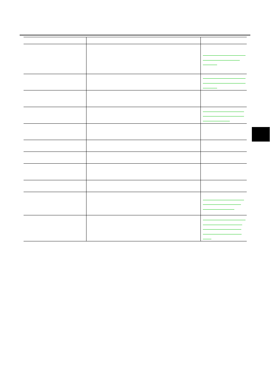
CAN COMM CIRCUIT
[U1000]
●
CAN communication line is open or shorted.
●
ABS actuator and electric unit (control unit) internal malfunc-
tion
●
Battery voltage for EMC is suddenly interrupted for approxi-
mately 0.5 seconds or more.
BRC-139, "Inspection 13
CAN Communication
System"
(Note 2)
BR FLUID LEVEL LOW
[C1155]
Brake fluid level drops or circuit between ABS actuator and elec-
tric unit (control unit) and brake fluid level switch is open or
shorted.
BRC-138, "Inspection 11
Brake Fluid Level Sensor
System"
VARIANT CODING
[C1170]
V coding is not functioning.
ABS actuator and elec-
tric unit (control unit) and
circuit
G - SENSOR
[C1113]
Decel G sensor is malfunctioning, or signal line of Decel G sen-
sor is open or shorted.
BRC-132, "Inspection 6
Yaw Rate/Side/Decel G
sensor System"
ENGINE SIGNAL 1
[C1130]
Based on the signal from ECM, ABS actuator and electric unit
(control unit) judges that engine fuel cut system is malfunction-
ing.
–
ENGINE SIGNAL 2
[C1131]
Based on the signal from ECM, ABS actuator and electric unit
(control unit) judges that engine ETC system is malfunctioning.
–
ENGINE SIGNAL 3
[C1132]
Based on the signal from ECM, ABS actuator and electric unit
(control unit) judges that engine CAN system is malfunctioning.
–
ENGINE SIGNAL 4
[C1133]
Based on the signal from ECM, ABS actuator and electric unit
(control unit) judges that engine torque down system is malfunc-
tioning.
–
ENGINE SIGNAL 6
[C1136]
Based on the signal from ECM, ABS actuator and electric unit
(control unit) judges that engine control system is malfunctioning.
–
ACTUATOR RLY
[C1140]
●
Actuator solenoid valve relay is ON, even if control unit sends
off signal.
●
Actuator solenoid valve relay is OFF, even if control unit sends
on signal.
BRC-135, "Inspection 8
Actuator Motor, Motor
Relay, and Circuit"
DECEL G SEN SET
[C1160]
Neutral position correction of Decel G -sensor is not finished.
BRC-140, "Inspection 14
When “DECEL G SEN
SET” Appears on Self-
Diagnosis Results Dis-
play"
Self-diagnostic item
Malfunction detecting condition
Check system