Nissan Murano Z50 (2003 year). Manual - part 52


  Index      Manuals     Nissan Murano Z50 (2003 year) - Service and Repair Manual


Search            copyright infringement  


Content      ..     50      51      52      53     ..


Nissan Murano Z50 (2003 year). Manual - part 52


TROUBLE DIAGNOSIS

BRC-53

[ABS]

C

D

E

G

H

I

J

K

L

M

A

B

BRC

Revision; 2004 April

2003 Murano

6. 

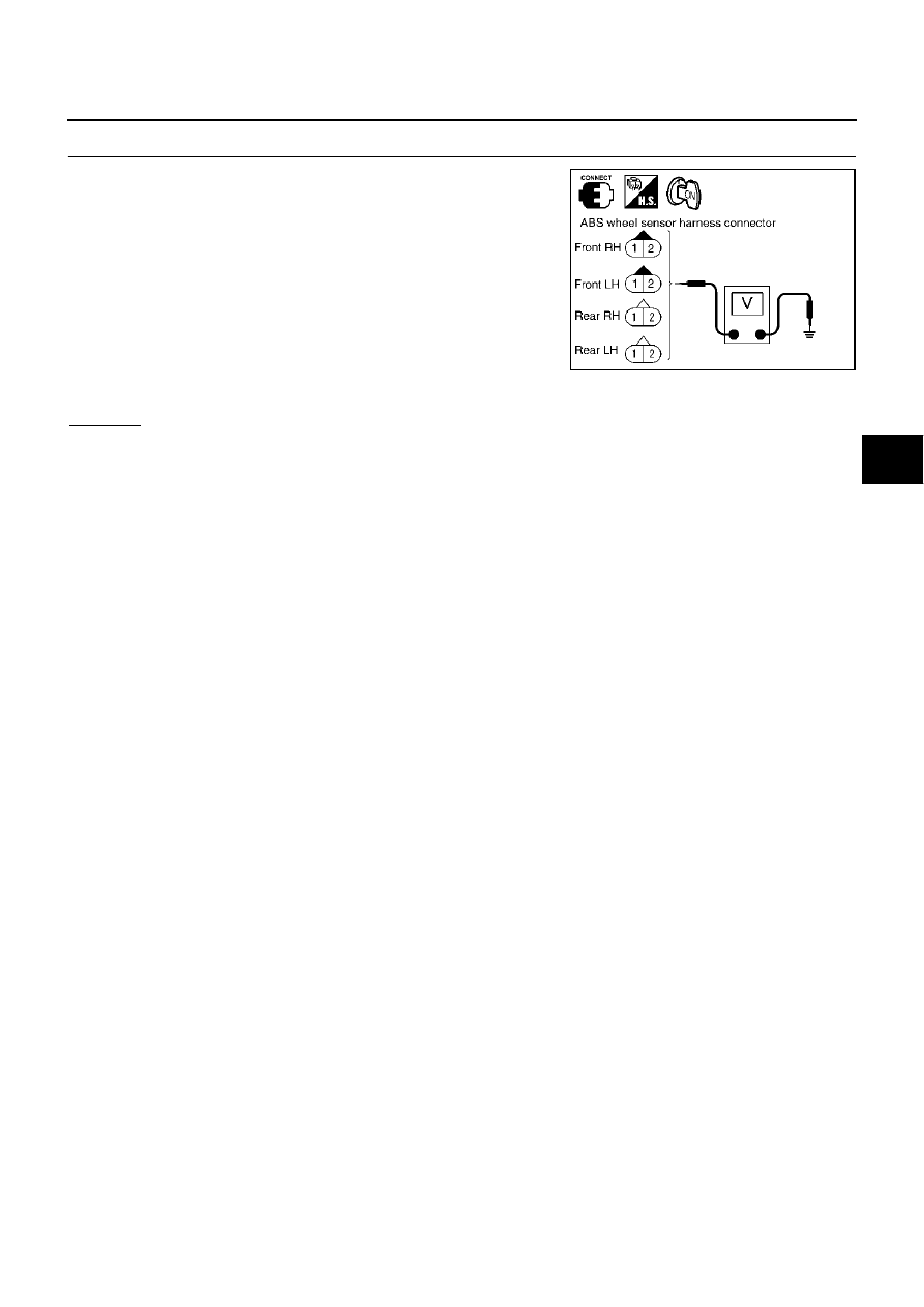
CHECK WHEEL SENSOR POWER SUPPLY CIRCUIT

1.

Connect wheel sensor connector E20 (FR - LH), E27 (FR - RH),
B202 (RR - LH), B203 (RR - RH) and ABS actuator and electric
unit (control unit) connector E24.

2.

Turn ignition switch ON and check voltage between power sup-
ply terminal and ground.

OK or NG

OK

>> Replace wheel sensor.

NG

>> Replace ABS actuator and electric unit (control unit).

Voltage

Front RH

1 (B) - Ground

: 8 V or more

Front LH

1 (G) - Ground

: 8 V or more

Rear RH 

1 (LG) - Ground

: 8 V or more

Rear LH 

1 (L) - Ground

: 8 V or more

PFIA0427E

BRC-54

[ABS]

TROUBLE DIAGNOSIS

Revision; 2004 April

2003 Murano

Inspection 2 ABS Actuator and Electric Unit (Control Unit)

AFS0018X

INSPECTION PROCEDURE

1. 

CHECK SELF-DIAGNOSIS RESULT

Check self-diagnosis results.

Is above displayed in self-diagnosis display items?

YES

>> Replace ABS actuator and electric unit (control unit). Re-conduct ABS actuator and electric unit

(control unit) self-diagnosis.

NO

>> Inspection END

Self-diagnosis results

CONTROLLER FAILURE

TROUBLE DIAGNOSIS

BRC-55

[ABS]

C

D

E

G

H

I

J

K

L

M

A

B

BRC

Revision; 2004 April

2003 Murano

Inspection 3 Solenoid Valve System

AFS0018Z

INSPECTION PROCEDURE

1. 

CHECK SELF-DIAGNOSIS RESULT

Check self-diagnosis results.

Is above displayed in self-diagnosis item?

YES

>> GO TO 2.

NO

>> Inspection END

2. 

CHECK CONNECTOR

1.

Disconnect ABS actuator and electric unit (control unit) connector E24, check terminal for is deformation,
disconnection, looseness, etc., and if there is any malfunction, repair or replace terminal.

2.

Securely reconnect connector and perform self-diagnosis.

OK or NG

OK

>> Connector terminal contact is loose, damaged, open or shorted.

NG

>> GO TO 3.

3. 

CHECK ABS ACTUATOR RELAY OR ABS MOTOR RELAY POWER SUPPLY CIRCUIT

1.

Disconnect ABS actuator and electric unit (control unit) connector E24.

2.

Check voltage between ABS actuator and electric unit (control
unit) harness connector E24.

OK or NG

OK

>> GO TO 4

NG

>> Circuit malfunction between battery and ABS actuator and electric unit (control unit). Repair the

circuit.

Self-diagnosis results

FR LH IN ABS SOL

FR LH OUT ABS SOL

RR RH IN ABS SOL 

RR RH OUT ABS SOL 

FR RH IN ABS SOL

FR RH OUT ABS SOL

RR LH IN ABS SOL

RR LH OUT ABS SOL

PFIA0428E

ABS actuator and electric unit 

(Control unit)

Ground

Voltage

1 (G/R)

Battery voltage (approx. 12 V)

32 (R/B)

Battery voltage (approx. 12 V)

BRC-56

[ABS]

TROUBLE DIAGNOSIS

Revision; 2004 April

2003 Murano

4. 

CHECK ABS ACTUATOR AND ELECTRIC UNIT (CONTROL UNIT) GROUND CIRCUIT

Check ABS actuator and electric unit (control unit) ground circuit.

OK or NG

OK

>> Perform self-diagnosis again. If the same results appear, replace ABS actuator and electric unit

(control unit).

NG

>> Open or short in harness. Repair or replace harness.

Inspection 4 CAN Communication Lines

AFS002QS

INSPECTION PROCEDURE

1. 

CHECK CONNECTOR

1.

Turn ignition switch OFF, disconnect the ABS actuator and electric unit (control unit) connector E24, and
check the terminal for deformation, disconnection, looseness, and so on. If there is a malfunction, repair
or replace the terminal.

2.

Reconnect connector to perform self-diagnosis.

Is “CAN COMM CIRCUIT” displayed in the self-diagnosis display items?

YES

>> Print out the self-diagnostic results, and refer to 

LAN-10, "Precautions When Using CONSULT-II"

 .

NO

>> Connector terminal connector is loose, damaged, open, or shorted.

Inspection 5 Actuator Motor, Motor Relay, and Circuit

AFS001ZF

INSPECTION PROCEDURE

1. 

CHECK SELF-DIAGNOSIS RESULT (1)

Check self-diagnosis results.

Is above displayed in self-diagnosis display items?

YES

>> GO TO 2.

NO

>> Inspection END

2. 

CHECK SELF-DIAGNOSIS RESULT (2)

1.

Disconnect ABS actuator and electric unit (control unit) connector E24. Then reconnect it securely.

2.

Preform self-diagnosis again.

DO any self-diagnosis items appear?

YES

>> GO TO 3

NO

>> Poor connection. Repair or replace the applicable connector.

LFIA0152E

ABS actuator and electric unit

(Control unit)

Ground

Continuity

16 (B), 47 (B)

Yes

Self-diagnosis results

PUMP MOTOR

ACTUATOR RLY

TROUBLE DIAGNOSIS

BRC-57

[ABS]

C

D

E

G

H

I

J

K

L

M

A

B

BRC

Revision; 2004 April

2003 Murano

3. 

CHECKING ABS MOTOR AND MOTOR RELAY POWER SYSTEM

1.

Disconnect ABS actuator and electric unit (control unit) connector.

2.

Check voltage between ABS actuator and electric (control unit)
unit connector E24 and body ground.

3.

Check resistance between ABS actuator and electric unit (con-
trol unit) connector E24 and ground.

OK or NG

OK

>> Perform self-diagnosis again. If the same result

appears, replace ABS actuator and electric unit (control
unit). Refer to 

BRC-66, "ACTUATOR AND ELECTRIC

UNIT (ASSEMBLY)"

 .

NG

>> Repair harness or connectors.

Inspection 6 ABS Actuator and Electric Unit (Control Unit) Power Supply and 
Ground Circuit

AFS001ZG

INSPECTION PROCEDURE

1. 

CHECK SELF-DIAGNOSIS RESULT 

Check self-diagnosis results.

Dose “BATTERY VOLTAGE” appear in self-diagnosis results display?

YES

>> GO TO 2.

NO

>> Inspection END

2. 

CHECK SELF-DIAGNOSIS RESULT (2)

1.

Disconnect ABS actuator and electric unit (control unit) connector E24. Then reconnect it securely.

2.

Preform self-diagnosis again.

Do any self-diagnosis items appear?

YES

>> GO TO 3

NO

>> Poor connection. Repair or replace the applicable connector.

ABS actuator and electric 

unit (control unit)

Body ground

Voltage (V)

(Approx.)

1 (G/R), 32(R/B)

12 V

PFIA0455E

ABS actuator and electric 

unit (control unit)

Body ground

Resistance value (

)

(Approx.)

16 (B), 47 (B)

PFIA0456E

Self-diagnosis results

BATTERY VOLTAGE

BRC-58

[ABS]

TROUBLE DIAGNOSIS

Revision; 2004 April

2003 Murano

3. 

CHECK ABS MOTOR AND MOTOR RELAY POWER SYSTEM

1.

Disconnect ABS actuator and electric unit (control unit) connector.

2.

Check voltage between ABS actuator and electric unit (control
unit) connector E24 and body ground.

OK or NG

OK

>> GO TO 4. 

NG

>> GO TO 5.

4. 

CHECK ABS ACTUATOR AND ELECTRIC UNIT (CONTROL UNIT) GROUND CIRCUITS

Check resistance between ABS actuator and electric unit (control
unit) connector E24 and ground.

OK or NG

OK

>> Perform ABS actuator and electric unit (control unit) self-

diagnosis again.

NG

>> Repair harness or connectors.

5. 

CHECK ABS ACTUATOR AND ELECTRIC UNIT (CONTROL UNIT) POWER SYSTEM

1.

Check fuse.

2.

Check continuity between battery positive terminal and ABS
actuator and electric unit (control unit) connector E24.

OK or NG

OK

>> Check for non-standard condition in battery (terminal

looseness, low voltage, etc.) and alternator.

NG

>>

Replace fuse.

Open or short in harness.

ABS actuator and electric 

unit (control unit)

Body ground

Voltage (V)

(Approx.)

1(G/R),32 (R/B)

12 V

PFIA0455E

ABS actuator and electric 

unit (control unit)

Body ground

Resistance value (

)

(Approx.)

16 (B), 47 (B)

PFIA0456E

ABS actuator and electric 

unit (control unit)

Battery positive terminal

Continuity

1 (G/R), 32 (R/B)

YES

PFIA0457E

TROUBLE DIAGNOSIS

BRC-59

[ABS]

C

D

E

G

H

I

J

K

L

M

A

B

BRC

Revision; 2004 April

2003 Murano

Inspection 7 G Sensor System

AFS001ZH

INSPECTION PROCEDURE

1. 

CHECK SELF-DIAGNOSIS RESULT

Check self-diagnosis results.

Is above displayed in self-diagnosis display items?

YES

>> GO TO 2.

NO

>> Inspection END

2. 

CHECK G SENSOR

Use “Data Monitor” to check if the G sensor are normal. 

OK or NG

OK

>> Inspects End

NG

>> Replace ABS actuator and electric unit (control unit) and then re-conduct ABS actuator and elec-

tric unit (control unit) self-diagnosis.

Self-diagnosis results

G-SENSOR

Vehicle status

G sensor (Data monitor standard)

When stopped

–0.11 G to +0.11 G

Speed up

Negative value

Speed down

Positive value

BRC-60

[ABS]

TROUBLE DIAGNOSIS

Revision; 2004 April

2003 Murano

Symptom 1 Excessive ABS Function Operation Frequency

AFS00193

1. 

CHECK WHEEL SENSOR

Check Wheel Sensor

Sensor mount and damage inspection

Sensor rotor mount and damage inspection

Sensor connector connection inspection

Sensor harness inspection

OK or NG

OK

>> GO TO 2.

NG

>> Sensor or sensor rotor replacement

2. 

CHECK FRONT AND REAR AXLE

Make sure there is no excessive play in the front and rear axles.

OK or NG

OK

>> Refer to Symptom 2

NG

>> Repair.

3. 

CHECK ABS WARNING LAMP DISPLAY

Make sure the ABS warning lamp turns off approximately 2 second after the ignition switch is turned on or
when driving.

OK or NG

OK

>> Normal

NG

>> Perform self-diagnosis. Refer to 

BRC-43, "SELF-DIAGNOSIS"

 .

Symptom 2 Unexpected Pedal Action

AFS001ZI

1. 

CHECK BRAKE PEDAL STROKE

Check brake pedal stroke.

Is the stroke too long?

YES

>>

Bleed air from the brake piping.

Check the brake pedal, brake booster, and master cylinder mount for play, looseness, and
brake system for fluid leaks, etc. If any malfunctions are found, make repair.

NO

>> GO TO 2.

2. 

CHECK PEDAL FORCE

Check that brake is effective with pedal depressed.

Is pedal heavy but affective?

YES

>> Normal

NO

>> GO TO 3

3. 

CHECK PERFORMANCE

Disconnect ABS actuator and electric unit (control unit) connector E24 and make sure the braking force us
sufficient when ABS in not operating. After the inspection, reconnect connector.

OK or NG

OK

>> GO TO 4.

NG

>> Check brake system.

TROUBLE DIAGNOSIS

BRC-61

[ABS]

C

D

E

G

H

I

J

K

L

M

A

B

BRC

Revision; 2004 April

2003 Murano

4. 

CHECK ABS WARNING LAMP DISPLAY

Make sure the warning lamp turns OFF approximately 2 sec. After the ignition switch is turned ON or when
driving.

OK or NG

OK

>> Normal

NG

>> GO TO 5

5. 

CHECK WHEEL SENSOR

Wheel Sensor Inspection

Sensor mount and damage inspection

Sensor rotor mount and damage inspection

Sensor connector connection inspection

Sensor harness inspection

OK or NG

OK

>> Normal

NG

>> Sensor or sensor rotor replacement

Symptom 3 Long Stopping Distance

AFS001ZJ

CAUTION:

On slippery road surfaces, the stopping distance might be longer with ABS operating than when ABS
is not operating.

1. 

CHECK PERFORMANCE

Disconnect ABS actuator and electric unit (control unit) connector E24 to deactivate ABS. In this condition,
check stopping distance. After inspection, connect connector.

Is stopping distance still long?

YES

>>

Bleed air from the brake piping.

Check brake system.

NO

>> GO TO 2.

2. 

CHECK ABS WARNING LAMP DISPLAY

Make sure the ABS warning lamp turns OFF approximately 2 sec. After the ignition switch is turned ON or
when driving.

OK or NG

OK

>> Normal

NG

>> GO TO 3

3. 

CHECK WHEEL SENSOR

Wheel Sensor Inspection

Sensor mount and damage inspection

Sensor rotor mount and damage inspection

Sensor connector connection inspection

Sensor harness inspection

OK or NG

OK

>> Normal

NG

>> Sensor or sensor rotor replacement

BRC-62

[ABS]

TROUBLE DIAGNOSIS

Revision; 2004 April

2003 Murano

Symptom 4 ABS Function Dose Not Operate

AFS001ZK

CAUTION:

ABS does not operate when the speed is 10 km/h (6 MPH) or less.

1. 

CHECK ABS WARNING LAMP DISPLAY

Make sure the ABS warning lamp turns off approximately 2 second after the ignition switch is turned on or
when driving.

OK or NG

OK

>> GO TO 2.

NG

>> Perform self-diagnosis. Refer to 

BRC-41, "CONSULT- II Functions"

 . 

2. 

CHECK WHEEL SENSOR

Wheel Sensor Inspection

Sensor mount and damage inspection

Sensor rotor mount and damage inspection

Sensor connector connection inspection

Sensor harness inspection

OK or NG

OK

>> Normal

NG

>> Sensor or sensor rotor replacement

Symptom 5 Pedal Vibration or ABS Operation Sound Occurs

AFS001ZL

CAUTION:

Under the following conditions, when brake pedal is lightly depressed (just place a foot on it), ABS is
activated and vibration is felt. However, this is normal.

When shifting gears

When driving on slippery road

During cornering at high speed

When passing over bumps or grooves.

When driving just after starting engine (at approximately 10 km/h (6MPH) or higher)

1. 

SYMPTOM CHECK 1

Check if pedal vibration or operation sound occurs when the engine is started.

OK or NG

OK

>> Perform self-diagnosis. Refer to 

BRC-43, "SELF-DIAGNOSIS"

 .

NG

>> GO TO 2.

2. 

INSPECTION (1)

Does vibration occur during normal parking?

CAUTION:

In addition to activation for sudden braking, ABS may activate in conditions such as those listed 
below.

Roads with low surface.

Turning at high speed.

Passing through gusts of wind.

OK or NG

OK

>> GO TO 3.

NG

>> Normal

TROUBLE DIAGNOSIS

BRC-63

[ABS]

C

D

E

G

H

I

J

K

L

M

A

B

BRC

Revision; 2004 April

2003 Murano

3. 

INSPECTION (2)

Check for vibration when engine speed is increased while vehicle is stopped.

OK or NG

OK

>> GO TO 4

NG

>>

Normal

CAUTION:

Vibration may occur when vehicle is stopped.

4. 

INSPECTION (3)

Check for vibration when switches of electrical components are operated.

OK or NG

OK

>> Check for any wireless devices, or antenna lead near control unit (including wiring).

NG

>> GO TO 5.

5. 

CHECK ABS WARNING LAMP INDICATION

Confirm ABS warning lamp turns on.

OK or NG

OK

>> Execute self-diagnosis.

NG

>> GO TO 6.

6. 

CHECK WHEEL SENSORS

Inspect wheel sensor system.

Sensor mounting inspection.

Sensor pick-up inspection for iron chips.

Sensor connector engagement inspection.

Inspection of wheel sensor circuit.

OK or NG

OK

>> Normal

NG

>> Repair wheel sensor and sensor rotor system.

BRC-64

[ABS]

WHEEL SENSORS

Revision; 2004 April

2003 Murano

WHEEL SENSORS

PFP:47910

Removal and Installation

AFS00198

REMOVAL

Pay attention to the following when removing wheel sensor.

CAUTION:

As much as possible, avoid rotating wheel sensor when removing it. Pull wheel sensors out with-
out pulling on sensor harness.

Take care to avoid damaging wheel sensor edges or rotor teeth. Remove wheel sensor first before
removing front or rear wheel hub. This is to avoid damage to wheel sensor wiring and loss of sen-
sor function.

INSTALLATION

Pay attention to the following when installing wheel sensor. Tighten installation bolts and nuts to the specified
torques.

When installing, make sure there is no foreign material such as iron chips on and in the mounting hole of
the wheel sensor. Make sure no foreign material has been caught in the sensor rotor. Remove any foreign
material and clean the mount.

When installing wheel sensor, be sure to press rubber grommets in until they lock at locations shown
above in figure. When installed, harness must not be twisted. 

PFIA0417E

SENSOR ROTOR

BRC-65

[ABS]

C

D

E

G

H

I

J

K

L

M

A

B

BRC

Revision; 2004 April

2003 Murano

SENSOR ROTOR

PFP:47970

Removal and Installation

AFS00199

REMOVAL
Front

Sensor rotor cannot be disassembled. To replace sensor rotor, replace hub bearing assembly. Refer to 

FAX-5,

"FRONT WHEEL HUB AND KNUCKLE"

  in “FAX” section.

Rear

Sensor rotor cannot be disassembled. To replace sensor rotor, replace hub bearing assembly. Refer to 

RAX-5,

"WHEEL HUB"

  in “RAX” section.

INSTALLATION
Front

Sensor rotor cannot be disassembled. To replace sensor rotor, replace hub bearing assembly. Refer to 

FAX-5,

"FRONT WHEEL HUB AND KNUCKLE"

  in “FAX” section.

Rear

Sensor rotor cannot be disassembled. To replace sensor rotor, replace hub bearing assembly. Refer to 

RAX-5,

"WHEEL HUB"

  in “RAX” section.

BRC-66

[ABS]

ACTUATOR AND ELECTRIC UNIT (ASSEMBLY)

Revision; 2004 April

2003 Murano

ACTUATOR AND ELECTRIC UNIT (ASSEMBLY)

PFP:47660

Removal and Installation

AFS0019A

Pay attention to the following when removing actuator.

CAUTION:

Before servicing, disconnect battery cables.

To remove brake tube, use flare nut wrench to prevent flare nuts and brake tube from being dam-
aged. To install, use flare nut wrench (commercial service tool).

Do not remove and install actuator by holding harness.

After work is completed, bleed air from brake piping. Refer to 

BR-12, "Bleeding Brake System"

 .

PFIA0418E

1.

To front left

2.

To rear right

3.

To rear left

4.

To front right

5.

From master cylinder secondary 
side

6.

From master cylinder primary side

7.

ABS actuator and electric unit (con-
trol unit)

8.

Harness connector

PRECAUTIONS

BRC-67

[VDC/TCS/ABS]

C

D

E

G

H

I

J

K

L

M

A

B

BRC

Revision; 2004 April

2003 Murano

[VDC/TCS/ABS]

PRECAUTIONS

PFP:00001

Precautions for Supplemental Restraint System (SRS) “AIR BAG” and “SEAT 
BELT PRE-TENSIONER”

AFS001AI

The Supplemental Restraint System such as “AIR BAG” and “SEAT BELT PRE-TENSIONER”, used along
with a front seat belt, helps to reduce the risk or severity of injury to the driver and front passenger for certain
types of collision. This system includes seat belt switch inputs and dual stage front air bag modules. The SRS
system uses the seat belt switches to determine the front air bag deployment, and may only deploy one front
air bag, depending on the severity of a collision and whether the front occupants are belted or unbelted.
Information necessary to service the system safely is included in the SRS and SB section of this Service Man-
ual.

WARNING:

To avoid rendering the SRS inoperative, which could increase the risk of personal injury or death
in the event of a collision which would result in air bag inflation, all maintenance must be per-
formed by an authorized NISSAN/INFINITI dealer.

Improper maintenance, including incorrect removal and installation of the SRS, can lead to per-
sonal injury caused by unintentional activation of the system. For removal of Spiral Cable and Air
Bag Module, see the SRS section.

Do not use electrical test equipment on any circuit related to the SRS unless instructed to in this
Service Manual. SRS wiring harnesses can be identified by yellow and/or orange harnesses or
harness connectors.

Precautions for Brake System

AFS001ZP

Recommended fluid is brake fluid “DOT 3”.

Do not reuse drained brake fluid.

Be careful not to splash brake fluid on painted areas.

To clean or wash all parts of master cylinder, disc brake caliper and wheel cylinder, use clean brake fluid.

Never use mineral oils such as gasoline or kerosene. They will ruin rubber parts of the hydraulic system.

Use flare nut wrench when removing and installing brake tube.

Always torque brake lines when installing.

Before working, turn ignition switch OFF and disconnect electri-
cal connectors of ABS actuator and electric unit (control unit) or
battery terminals.

Burnish the brake contact surfaces after refinishing or replacing
drums or rotors, after replacing pads or linings, or if a soft pedal
occurs at very low mileage.
Refer to 

BR-32, "BRAKE BURNISHING PROCEDURE"

 .

WARNING:

Clean brake pads and shoes with a waste cloth, then wipe
with a dust collector.

Precautions for Brake Control

AFS001AL

During ABS operation, brake pedal lightly vibrates and a mechanical noise may be heard. This is normal.

Just after starting vehicle after ignition switch ON, brake pedal may vibrate or motor operating noise may
be heard from engine compartment. This is a normal status of operation check.

Stopping distance may be longer than that of vehicles without ABS when vehicle drives on rough, gravel,
or snow-covered (fresh, deep snow) roads.

When an error is indicated by ABS or another warning lamp, collect all necessary information from cus-
tomer (what symptoms are present under what conditions) and check for simple causes before starting
diagnostic servicing. Besides electrical system inspection, check brake booster operation, brake fluid
level, and fluid leaks.

If tire size and type are used in an improper combination, or brake pads are not Genuine NISSAN parts,
stopping distance or steering stability may deteriorate.

If there is a radio, antenna, or antenna lead-in wire (including wiring) near control module, ABS function
may have a malfunction or error.

SBR686C

BRC-68

[VDC/TCS/ABS]

PRECAUTIONS

Revision; 2004 April

2003 Murano

If aftermarket parts (car stereo, CD player, etc.) have been installed, check for incidents such as harness
pinches, open circuits, and improper wiring.

If the following components are replaced with non-genuine components or converted, the VDC OFF indi-
cator lamp and SLIP indicator lamp may turn on or the VDC system may not operate properly. Compo-
nents related to suspension (Shock Absorber, Strut, Spring, Bush, etc.), Tires, wheels (exclude specified
size), components related to brake (Pad, Rotor, Caliper, etc.), Components related to engine (Muffler,
ECM, etc.), Components related to body reinforcement (Roll bar, Tower bar, etc.).

Driving in the condition of breakage or excessive wear of the suspension, tires or components related to
the brakes may cause the VDC OFF indicator lamp and the SLIP indicator lamp to turn on, and the   VDC
system may not operate properly.

When the TCS or VDC is activated by sudden acceleration or sudden turn, some noise may occur. The
noise is a result of the normal operation of the TCS and VDC.

When driving on roads which have extreme slopes (such as mountainous roads) or high banks (such as
sharp carves on a freeway), the VDC may not operate normally, or the VDC warning lamp and the SLIP
indicator lamp may turn on. However, this is not a problem if normal operation can be resumed after
restarting the engine.

Sudden turns (such as spin turns, acceleration turns), drifting, etc. When VDC function is OFF (VDC SW
ON) may cause the yaw rate/side G -sensor system indicate a problem. However this is not a problem if
normal operation can be resumed after restarting the engine.

Diagnosis Precaution

AFS001AM

CAN SYSTEM

Do not apply voltage of 7.0 V or higher to terminal to be measured.

Maximum open terminal voltage of tester in use shall be 7.0 V or lower.

Before checking harnesses, turn ignition switch to OFF and disconnect battery negative cable.

Precaution for Harness Repair

AFS001AN

CAN SYSTEM

Area to be repaired shall be soldered, and wrapped with a tape
(be sure that fraying of twisted wire shall be within 110 mm 4.33
in)).

Do not make a bypass connection to repaired area. (If it is done,
branch part will be removed and characteristics of twisted wire
will be lost.)

PKIA0306E

PKIA0307E


Content      ..     50      51      52      53     ..