Nissan Murano Z50 (2003 year). Manual - part 48
FRONT DISC BRAKE
BR-29
C
D
E
G
H
I
J
K
L
M
A
B
BR
Revision; 2004 April
2003 Murano
INSTALLATION
CAUTION:
●
Refill with new brake fluid “DOT3”
●
Do not reuse drained brake fluid.
1.
Install disc rotor.
2.
Install caliper assembly to the vehicle, and tighten bolts to the
specified torque.
CAUTION:
Before installing caliper assembly to the knuckle, wipe off
oil the knuckle spindle washers and mounting surface of
caliper assembly.
3.
Install brake hose to the brake caliper assembly, and tighten
union bolts to the specified torque.
CAUTION:
●
Do not reuse the copper washer for union bolts.
●
Attach the brake hose to the brake hose mounting boss.
4.
Refill new brake fluid and bleed air. Refer to
BR-12, "Bleeding Brake System"
5.
Install the tires to the vehicle.
Disassembly and Assembly of Brake Caliper Assembly
AFS0017F
DISASSEMBLY
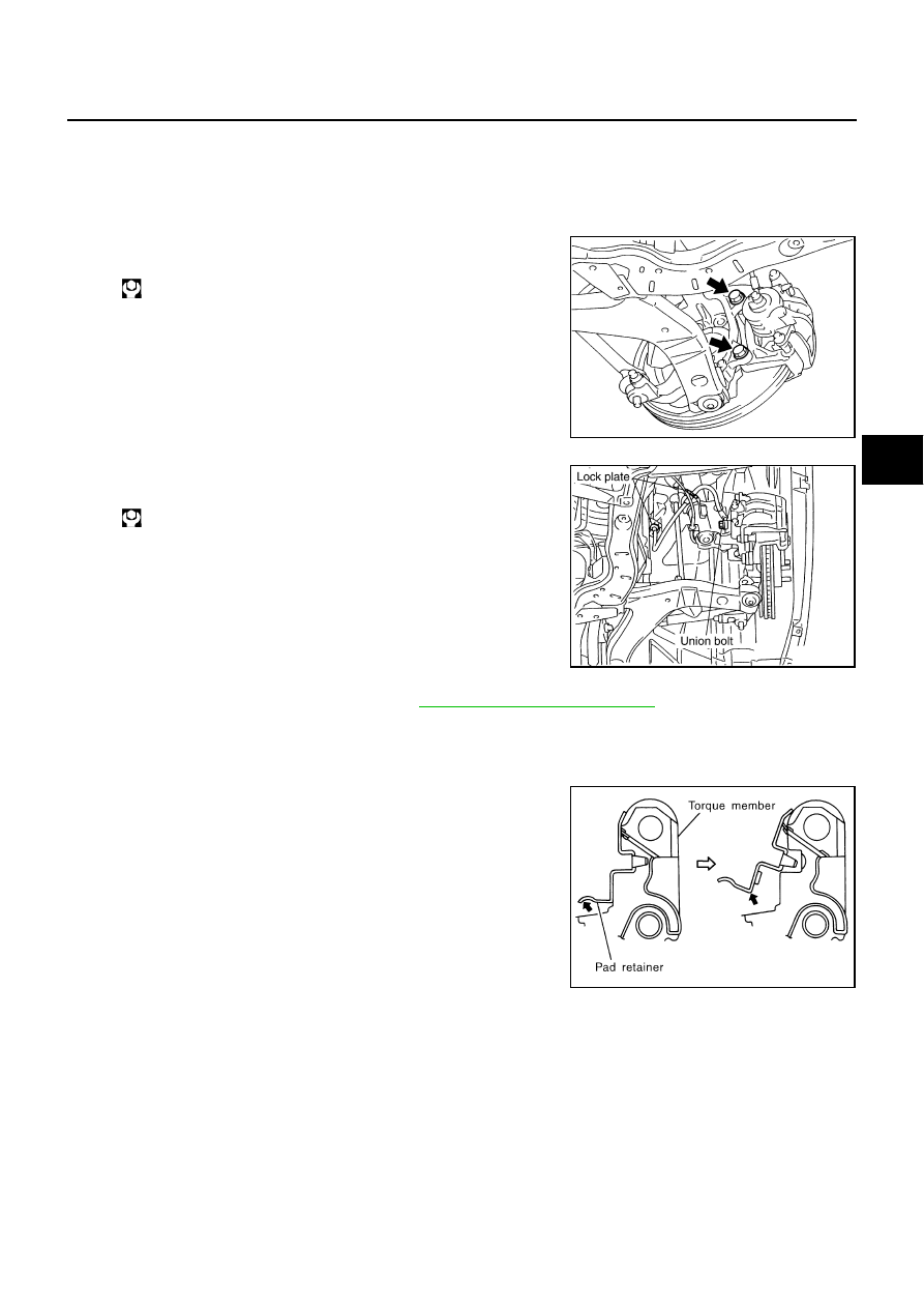
1.
Remove slide pin bolts, and then remove the pads, shim, shim
cover, and pad retainers from torque member.
CAUTION:
When removing the pad retainer from the torque member,
lift it in the direction indicated by the arrow in the figure so
that it does not deform.
2.
Remove sliding pins and sliding pin boots from torque member.
: 137 - 176 N·m (14 - 17 kg-m, 101 - 129 ft-lb)
PFIA0411E
: 16.7 - 19.6 N·m (1.7 - 1.9 kg-m, 13 - 14 ft-lb)
PFIA0404E
SBR556E