Nissan Murano Z50 (2003 year). Manual - part 38
FRONT DOOR LOCK
BL-131
C
D
E
F
G
H
J
K
L
M
A
B
BL
Revision; 2004 April
2003 Murano
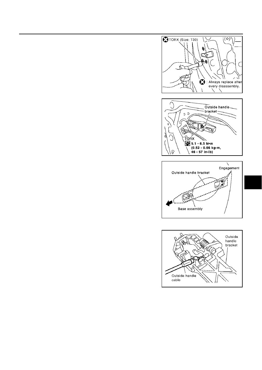
9.
Remove the TORX bolts (T30), remove the door lock assembly.
10. Remove the TORX bolt (T30) of the outside handle bracket.
11. While pulling outside handle bracket, slide toward rear of vehicle
to remove outside handle bracket.
12. Disconnect the door lock actuator connector and remove the door lock assembly.
13. Reach to separate the outside handle cable connection.
INSTALLATION
Install in the reverse order of removal.
CAUTION:
To install each rod, be sure to rotate the rod holder until a click is felt.
PIIA1090E
PIIA3556E
PIIA3558E
PIIA5059E