Nissan Murano Z50 (2003 year). Manual - part 27
NAVIGATION SYSTEM
AV-225
C
D
E
F
G
H
I
J
L
M
A
B
AV
Revision; 2004 April
2003 Murano
Cause (condition)
–: While driving
ooo: Display
Driving condition
Remarks (correction, etc.)
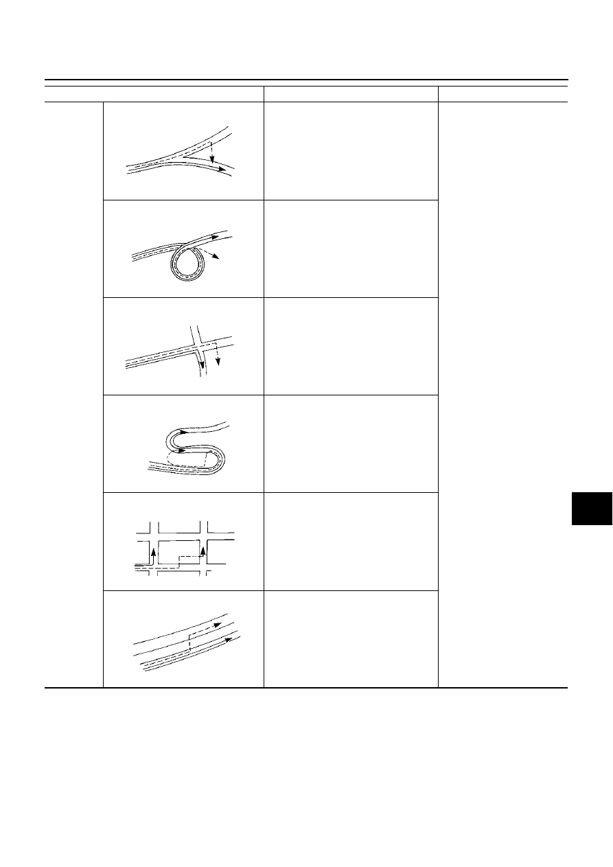
Road config-
uration
Y–intersections
At a Y intersection or similar gradual divi-
sion of roads, error the direction of travel
deduced by the sensor may result in the
current-location mark appearing on the
wrong road.
If after travelling about 10 km (6
miles) the correct location has
not been restored, perform
location correction and, if nec-
essary, direction correction.
Spiral roads
When driving on a large, continuous spiral
road (such as loop bridge), turning angle
error is accumulated and the vehicle mark
may deviate from the correct location.
Straight roads
When driving on a long, straight road and
slow curve without stopping, map-match-
ing does not work effectively enough and
distance errors may accumulate. As a
result, the vehicle mark may deviate from
the correct location when the vehicle
turned at a corner.
Zigzag roads
When driving on a zigzag road, the map
may be matched to other roads in the simi-
lar direction nearby at every turn, and the
vehicle mark may deviate from the correct
location.
Roads laid out in a grid pattern
When driving at where roads are laid out in
a grid pattern, where many roads are run-
ning in the similar direction nearby, the
map may be matched to them by mistake
and the vehicle mark may deviate from the
correct location.
Parallel roads
When two roads are running in parallel
(such as highway and sideway), the map
may be matched to the other road by mis-
take and the vehicle mark may deviate
from the correct location.
ELK0192D
ELK0193D
ELK0194D
ELK0195D
ELK0196D
ELK0197D