Nissan Murano Z50 (2003 year). Manual - part 26
NAVIGATION SYSTEM
AV-209
C
D
E
F
G
H
I
J
L
M
A
B
AV
Revision; 2004 April
2003 Murano
2.
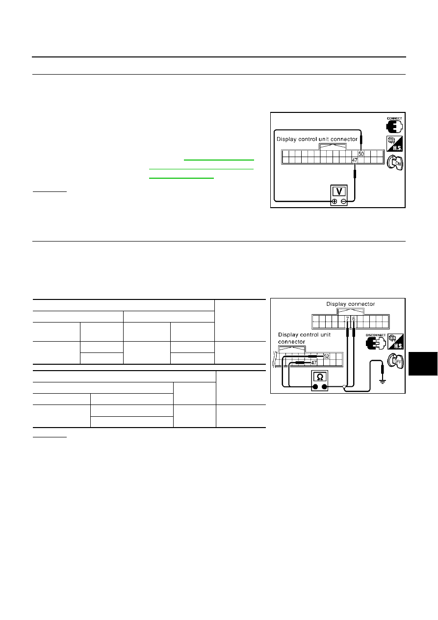
CHECK RGB SIGNAL
1.
Connect display control unit connector and display connector.
2.
Turn ignition switch ON.
3.
Display “Color bar” by “CONFIRMATION/ADJUSTMENT” mode.
4.
Check the following with CONSULT-ll or oscilloscope.
●
When the screen looks bluish.
Voltage signal between display control unit connector M43 ter-
minal 50 (G/Y) and 47.
OK or NG
OK
>> Replace display.
NG
>> Replace display control unit.
Color of RGB Image is Not Proper (Excepting NAVI Screen Looks Reddish)
AKS005SS
1.
CHECK RGB HARNESS
1.
Turn ignition switch OFF.
2.
Disconnect display control unit connector and display connector.
3.
Check continuity between display control unit and display.
4.
Check continuity between display control unit and ground.
●
When the screen looks reddish.
OK or NG
OK
>> GO TO 2.
NG
>> Repair harness or connector.
50 (G/Y) – 47
and Reference Value for Dis-
play Control unit"
SKIA4697E
Terminals
Continuity
Display control unit (+)
Display (–)
Connector
Terminal
(Wire color)
Connector
Terminal
(Wire color)
M43
52 (G/R)
M38
6 (G/R)
Yes
47
7
Terminals
Continuity
Display control unit (+)
(–)
Connector
Terminal (Wire color)
M43
52 (G/R)
Ground
No
47
SKIA4354E