Nissan Murano Z50 (2003 year). Manual - part 15


  Index      Manuals     Nissan Murano Z50 (2003 year) - Service and Repair Manual


Search            copyright infringement  


Content      ..     13      14      15      16     ..


Nissan Murano Z50 (2003 year). Manual - part 15


AUDIO

AV-33

C

D

E

F

G

H

I

J

L

M

A

B

AV

Revision; 2004 April

2003 Murano

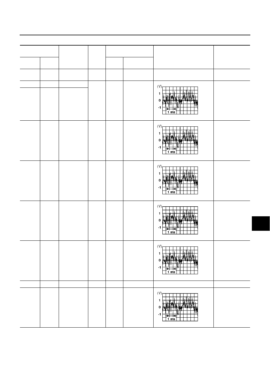
Terminals and Reference Value for BOSE Speaker Amp.

AKS005F0

Terminal

(Wire color)

Item

Signal 

input/

output

Condition

Reference value

Example of

symptom

+

Ignition 

switch

Operation

1 (Y)

Ground

Battery power 
supply

Input

OFF

Battery voltage

System does not 
work properly.

18 (W)

2 (B)

Woofer 1

Output

ON

Receive audio 
signal

No sound from 
woofer

19 (B/P)

3 (O)

Woofer 2

9 (G)

10 (B/Y)

Rear door 
speaker LH

Output

ON

Receive audio 
signal

No sound from 
rear speaker LH

11 (L)

12 (R)

Rear door 
speaker RH

Output

ON

Receive audio 
signal

No sound from 
rear speaker RH

13 (L/R)

14 (L/B)

Front door 
speaker LH 
and tweeter 
LH

Output

ON

Receive audio 
signal

No sound from 
front door speaker 
LH or tweeter LH

15 (W/B)

16 (G/B)

Front door 
speaker RH 
and tweeter 
RH

Output

ON

Receive audio 
signal

No sound from 
front door speaker 
RH or tweeter RH

17 (B)

Ground

Ground

ON

Approx. 0V

24 (L)

23 (B/W)

Audio sound 
signal rear RH

Input

ON

Receive audio 
signal

No sound from 
rear speaker RH

SKIA0177E

SKIA0177E

SKIA0177E

SKIA0177E

SKIA0177E

SKIA0177E

AV-34

AUDIO

Revision; 2004 April

2003 Murano

A/C and AV Switch Self-Diagnosis Function

AKS005RI

It can check ON/OFF operation of each switch in the A/C and AV switch and diagnose the input signals to the
steering switch.

STARTING THE SELF-DIAGNOSIS MODE

1.

Turn ignition switch from OFF to ACC.

2.

Within 10 seconds press and hold the switches “PAUSE/MUTE”
and “PREV ”simultaneously for 3 seconds.

Then the self-diagnosis operates.

EXITING THE SELF-DIAGNOSIS MODE

Turn ignition switch OFF. Then the self-diagnosis ends.

DIAGNOSIS FUNCTION 

It can illuminate all the indicators (LED) in the A/C and AV switch.

It can check for continuity of the switches by sounding the buzzer when the A/C and AV switch is pressed.

It can check for continuity of harness between A/C and AV switch and steering switch.

26 (O)

25 (Y)

Audio sound 
signal rear LH

Input

ON

Receive audio 
signal

No sound from 
rear speaker LH

28 (Y)

27 (BR)

Audio sound 
signal front RH

Input

ON

Receive audio 
signal

No sound from 
front door speaker 
RH or tweeter RH

30 (W)

29 (B)

Audio sound 
signal front LH

Input

ON

Receive audio 
signal

No sound from 
front door speaker 
LH or tweeter LH

31

(G/W)

Ground

Control (sub+)

Input

ON

Approx. 12V

System does not 
work properly.

Terminal

(Wire color)

Item

Signal 

input/

output

Condition

Reference value

Example of

symptom

+

Ignition 

switch

Operation

SKIA0177E

SKIA0177E

SKIA0177E

SKIA4385E

AUDIO

AV-35

C

D

E

F

G

H

I

J

L

M

A

B

AV

Revision; 2004 April

2003 Murano

Trouble Diagnosis

AKS005F2

The majority of the audio malfunctions are the result of outside causes (bad CD/cassette, electromagnetic
interference, etc.). Check the symptoms below to diagnose the malfunction.

MALFUNCTION WITH RADIO AND CD (BASE SYSTEM)

Make sure that operation excepting audio system can be done with A/C and AV switch. If not, refer 

AV-103,

"Trouble Diagnosis Chart by Symptom"

  to repair malfunctioning parts.

MALFUNCTION WITH RADIO, TAPE AND CD (BOSE SYSTEM)

Make sure that operation excepting audio system can be done with A/C and AV switch. If not, refer 

AV-103,

"Trouble Diagnosis Chart by Symptom"

  (Without navigation system), 

AV-218, "Unable to Operate All of A/C

and AV Switches (Unable to Start Self-Diagnosis)"

  (With navigation system) to repair malfunctioning parts.

Symptom

Possible cause

Inoperative

Audio unit power supply circuit. Refer to 

AV-38, "Power Supply Circuit 

Inspection"

 .

Audio communication line. Refer to 

AV-40, "Audio Communication Line 

Check (Without Navigation System)"

 .

A/C and AV switch check. Refer to 

AV-40, "A/C and AV Switch Check"

 .

If above system is OK, replace audio unit.

Steering switch dose not operate

Steering switch check. Refer to 

AV-39, "Steering Switch Check"

 .

A/C and AV switch check. Refer to 

AV-40, "A/C and AV Switch Check"

 .

If above systems are OK, replace audio unit.

All speaker do not sound

Replace audio unit. Refer to 

AV-55, "Removal and Installation of Audio Unit"

 .

One or several speaker does not sound

Front door speaker check. Refer to 

AV-41, "Front Door Speaker Check 

(Base System)"

 .

Rear door speaker check. Refer to 

AV-43, "Rear Door Speaker Check (Base 

System)"

 .

If above system is OK, replace door speaker.

Poor sound

Audio unit

Speaker

Noisy

Audio unit

Each electrical equipment

Symptom

Possible cause

Inoperative

Audio unit power supply circuit. Refer to 

AV-38, "Power Supply Circuit 

Inspection"

 .

Audio communication line (Without navigation system). Refer to 

AV-40, 

"Audio Communication Line Check (Without Navigation System)"

 .

Audio communication line (With navigation system). Refer to 

AV-41, "Audio 

Communication Line Check (With Navigation System)"

 .

A/C and AV switch check. Refer to 

AV-40, "A/C and AV Switch Check"

 .

If above system is OK, replace audio unit.

Steering switch dose not operate

Steering switch check. Refer to 

AV-39, "Steering Switch Check"

 .

A/C and AV switch check. Refer to 

AV-40, "A/C and AV Switch Check"

 .

If above systems are OK, replace audio unit.

All speaker do not sound

Replace audio unit. Refer to 

AV-55, "Removal and Installation of Audio Unit"

 .

One or several speaker does not sound

Front door speaker check. Refer to 

AV-45, "Front Door Speaker Check 

(BOSE System)"

 . 

Rear door speaker check. Refer to 

AV-49, "Rear Door Speaker Check 

(BOSE System)"

 . 

If above system is OK, replace BOSE speaker amp.

Woofer check. Refer to 

AV-53, "Woofer Check (BOSE System)"

If above system is OK, replace woofer.

AV-36

AUDIO

Revision; 2004 April

2003 Murano

FOR RADIO ONLY 

NOTE:
1.

This is noise resulting from variations in field strength, such as fading noise and multi-path noise, or exter-
nal noise from trains and other sources. It is not a malfunction.

Fading noise: This noise occurs because of variations in the field strength in a narrow range due to moun-
tains or buildings blocking the signal.

Multi-path noise: This noise results from the waves sent directly from the broadcast station arriving at the
antenna at a different time from the waves which reflect off of mountains or buildings.

FOR CASSETTE PLAYER ONLY

FOR CD ONLY

Speed sensitive volume system dose not work

Vehicle speed signal check. Refer to 

AV-54, "Vehicle Speed Signal Check"

 .

If above system is OK, replace audio unit.

Poor sound

Audio unit

BOSE speaker amp. 

Speaker

Noisy

Audio unit

BOSE speaker amp. 

Each electrical equipment

Symptom

Possible cause

Symptom

Possible cause

No sound

Audio unit

Antenna feeder

Antenna amp.

Noisy

Audio unit

Antenna feeder

Antenna amp.

Noise prevention parts

Each electrical equipment

Wire harness of each piece of electrical equipment

Selected radio stations stored in memory are deleted

Audio unit

Symptom

Possible cause

Cassette tape cannot be inserted

Cassette tape

Audio unit

Cassette tape cannot be ejected

Auto reverse does not work, or the tape direction changes in 
the middle of play

There is much noise

The sound is not clear

Sound fluctuates/tape speed not correct

No sound

Symptom

Possible cause

CD cannot be inserted

CD

Audio unit

CD cannot be ejected

The CD cannot be played

The sound skips, stops suddenly, or is distorted

AUDIO

AV-37

C

D

E

F

G

H

I

J

L

M

A

B

AV

Revision; 2004 April

2003 Murano

Noise Inspection

AKS005F3

The vehicle itself can be a source of noise if noise prevention parts or electrical equipment is malfunction.
Check if noise is caused and/or changed by engine speed, ignition switch turned to each position, and opera-
tion of each piece of electrical equipment, and determine the cause.

NOTE:
The source of the noise can be found easily by listening to the noise while removing the fuses of electrical
components, one by one.

TYPE OF NOISE AND POSSIBLE CAUSE 

Occurrence condition

Possible cause

Occurs only when engine is ON.

A continuous growling noise occurs. The speed of 
the noise varies with changes in the engine speed.

Ignition condenser

A whistling noise occurs while the engine speed is 
high. A booming noise occurs while the engine is 
running and the lighting switch is ON.

Alternator

The occurrence of the noise is linked with the operation of the fuel pump.

Fuel pump condenser

Noise only occurs when various 
electrical components are oper-
ating.

A cracking or snapping sound occurs with the 
operation of various switches.

Relay malfunction, radio malfunction

The noise occurs when various motors are operat-
ing.

Motor case ground

Motor

The noise occurs constantly, not just under certain conditions.

Rear defogger coil malfunction

Open circuit in printed heater

Poor ground of antenna amplifier or 
antenna feeder line

A cracking or snapping sound occurs while the vehicle is being driven, especially 
when it is vibrating excessively.

Ground wire of body parts

Ground due to incorrect installation of parts

Wiring connections or a short circuit

AV-38

AUDIO

Revision; 2004 April

2003 Murano

Power Supply Circuit Inspection

AKS005F4

1. 

CHECK FUSE

Make sure that the following fuses of the BOSE speaker amp. and audio unit are not blown.

OK or NG

OK

>> GO TO 2.

NG

>> If fuse is blown, be sure to eliminate cause of malfunction before installing new fuse. Refer to 

PG-

3, "POWER SUPPLY ROUTING CIRCUIT"

 .

2. 

POWER SUPPLY CIRCUIT CHECK

1.

Check voltage between audio unit and ground.

2.

Check voltage between BOSE speaker amp. and ground.

OK or NG

OK

>>

INSPECTION END (Base system)

GO TO 3 (BOSE system).

NG

>>

Check connector housings for disconnected or loose terminals.

Repair harness or connector.

Unit

Terminals

Signal name

Fuse No.

Audio unit

6

Battery power

38

10

Ignition switch ACC or ON

6

BOSE speaker amp.

1

Battery power

38

Unit

Terminal No.

OFF

ACC

ON

(+)

(-)

Connector

Terminal 

(wire color)

Audio unit

M44

6 (Y)

Ground

Battery 
voltage

Battery 
voltage

Battery 
voltage

10 (P/B)

Ground

0 V

Battery 
voltage

Battery 
voltage

SKIA8743E

Unit

Terminal No.

OFF

ACC

ON

(+)

(-)

Connector

Terminal 

(wire color)

BOSE 
speaker 
amp.

B114

1(Y)

Ground

Battery 
voltage

Battery 
voltage

Battery 
voltage

SKIA9395E

AUDIO

AV-39

C

D

E

F

G

H

I

J

L

M

A

B

AV

Revision; 2004 April

2003 Murano

3. 

GROUND CIRCUIT CHECK

1.

Turn ignition switch OFF.

2.

Disconnect BOSE speaker amp. connector.

3.

Check continuity between BOSE speaker amp. harness connec-
tor B114 terminal 17 (B) and ground.

OK or NG

OK

>> INSPECTION END

NG

>>

Check connector housings for disconnected or loose
terminals.

Repair harness or connector.

Steering Switch Check

AKS0069B

1. 

A/C AND AV SWITCH SELF-DIAGNOSIS FUNCTION CHECK

1.

Start A/C and AV switch self-diagnosis function. Refer to 

AV-34, "A/C and AV Switch Self-Diagnosis Func-

tion"

 .

2.

Operate steering switch.

Does steering switch operate normally?

YES

>> INSPECTION END

NO

>> GO TO 2.

2. 

CHECK HARNESS

1.

Turn ignition switch OFF.

2.

Disconnect A/C and AV switch connector and spiral cable connector.

3.

Check continuity between spiral cable harness connector terminal and A/C and AV switch harness con-
nector terminal.

4.

Check continuity between A/C and AV switch and ground.

OK or NG

OK

>> GO TO 3.

NG

>> Repair harness.

Continuity should exist.

SKIA4312E

Terminals

Continuity

Spiral cable

A/C and AV switch 

Connector

Terminal

Connector

Terminal (Wire color)

M31

32 (G)

M48

13 (G)

Yes

31(B/W)

14 (B/W)

Yes

24 (R)

12 (R)

Yes

Terminals

Continuity

A/C and AV switch (+)

(–)

Connector

Terminal (Wire color)

M48

12 (R)

Ground

No

13 (G)

14 (B/W)

SKIA5873E

AV-40

AUDIO

Revision; 2004 April

2003 Murano

3. 

SPIRAL CABLE CHECK

1.

Disconnect spiral cable connector.

2.

Check continuity between spiral cable terminals.

OK or NG

OK

>> GO TO 4.

NG

>> Replace spiral cable.

4. 

CHECK STEERING SWITCH RESISTANCE

Check resistance steering switch terminals.

OK or NG

OK

>> INSPECTION END

NG

>> Replace steering switch.

A/C and AV Switch Check

AKS007H8

1. 

A/C AND AV SWITCH SELF-DIAGNOSIS FUNCTION CHECK

1.

Start A/C and AV switch self-diagnosis function. Refer to 

AV-34, "A/C and AV Switch Self-Diagnosis Func-

tion"

 .

2.

Operate voluntary switch.

Does A/C and AV switch operate normally?

YES

>> INSPECTION END

NO

>> Replace A/C and AV switch.

Audio Communication Line Check (Without Navigation System)

AKS005RJ

1. 

CHECK AUDIO COMMUNICATION LINE

Start audio communication line check. Refer to 

AV-40, "Audio Communication Line Check (Without Navigation

System)"

 .

OK or NG

OK

>> INSPECTION END

NG

>> Replace malfunctioning part.

Terminals

Continuity

Spiral cable

Connector

Terminal

Connector

Terminal

M31

32

M203

16

Yes

31

17

Yes

24

20

Yes

SKIA5874E

Terminal

Signal name

Condition

Resistance 

(

)

16

17

Seek down

Depress (station) down switch.

Approx.165

Power

Depress power switch.

Approx.0

Volume (down)

Depress volume down switch.

Approx.652

20

Seek up

Depress (station) up switch.

Approx.165

Mode

Depress mode switch.

Approx.0

Volume (up)

Depress volume up switch.

Approx.652

SKIA9400E

AUDIO

AV-41

C

D

E

F

G

H

I

J

L

M

A

B

AV

Revision; 2004 April

2003 Murano

Audio Communication Line Check (With Navigation System)

AKS005RK

1. 

CHECK AUDIO COMMUNICATION LINE

Start audio communication line check. Refer to 

AV-41, "Audio Communication Line Check (With Navigation

System)"

 .

OK or NG

OK

>> INSPECTION END

NG

>> Replace malfunctioning part.

Front Door Speaker Check (Base System)

AKS005FT

1. 

HARNESS CHECK

1.

Disconnect audio unit connector and front door speaker connector.

2.

Check continuity between audio unit harness connector terminal
and front door speaker harness connector terminal.

3.

Check continuity between audio unit harness connector terminal
and ground.

OK or NG

OK

>> GO TO  2.

NG

>>

Check connector housings for disconnected or loose terminals.

Repair harness or connector.

Terminals

Continuity

Audio unit 

Speaker 

Connector

Terminal

(Wire color)

Connector

Terminal

(Wire color)

M44

2 (W)

D5

1 (L/R)

Yes

1 (B)

2 (L/B)

4 (Y)

D34

1 (W/B)

3 (BR)

2 (G/B)

Terminals

Continuity

Audio unit 

Connector

Terminal (Wire color)

M44

2 (W)

Ground

No

1 (B)

4 (Y)

3 (BR)

SKIA4273E

AV-42

AUDIO

Revision; 2004 April

2003 Murano

2. 

FRONT SPEAKER SIGNAL CHECK

1.

Connect audio unit connector and front speaker connector.

2.

Turn ignition switch ON.

3.

Push  “POWER” switch.

4.

Check signal between audio unit harness connector terminal
and ground with CONSULT-II or oscilloscope.

OK or NG

OK

>> INSPECTION END

NG

>> Replace audio unit.

Terminals

Condi-

tion

Reference

signal

(+)

(-)

Con-

nec-

tor

Termi-

nal

(Wire 

color)

Con-

nec-

tor

Termi-

nal

(Wire 

color)

M44

2 (W)

M44

1 (B)

Receive 
audio 
signal

4 (Y)

3 (BR)

SKIA9401E

SKIA0177E

AUDIO

AV-43

C

D

E

F

G

H

I

J

L

M

A

B

AV

Revision; 2004 April

2003 Murano

Rear Door Speaker Check (Base System)

AKS005FU

1. 

HARNESS CHECK

1.

Disconnect audio unit connector and rear door speaker connector.

2.

Check continuity between audio unit harness connector terminal
and rear door speaker harness connector terminal.

3.

Check continuity between audio unit harness connector terminal
and ground.

OK or NG

OK

>> GO TO 2.

NG

>>

Check connector housings for disconnected or loose terminals.

Repair harness or connector.

Terminals

Continuity

Audio unit 

Speaker 

Connector

Terminal

(Wire color)

Connector

Terminal

(Wire color)

M45

13 (B/P)

D54

2 (R)

Yes

14 (O)

1(L)

15 (B/W)

D74

2 (R)

16 (L)

1 (L)

Terminals

Continuity

Audio unit 

Connector

Terminal (Wire color)

M45

13 (B/P)

Ground

No

14 (O)

15 (B/W)

16 (L)

SKIA4280E

AV-44

AUDIO

Revision; 2004 April

2003 Murano

2. 

REAR SPEAKER SIGNAL CHECK

1.

Connect audio unit connector and rear speaker connector.

2.

Turn ignition switch ON.

3.

Push  “POWER” switch.

4.

Check signal audio unit harness connector terminal with CON-
SULT-II or oscilloscope.

OK or NG

OK

>> INSPECTION END

NG

>> Replace audio unit.

Terminals

Condi-

tion

Reference

signal

(+)

(-)

Con-

nector

Termi-

nal

(Wire 

color)

Con-

nector

Termi-

nal

(Wire 

color)

M45

14

(O)

M45

13

(B/P)

Receive 
audio 
signal

16

(L)

15

(B/W)

SKIA9402E

SKIA0177E

AUDIO

AV-45

C

D

E

F

G

H

I

J

L

M

A

B

AV

Revision; 2004 April

2003 Murano

Front Door Speaker Check (BOSE System)

AKS005FV

1. 

HARNESS CHECK

1.

Disconnect BOSE speaker amp. connector and front door speaker connector.

2.

Check continuity between BOSE speaker amp. harness connec-
tor terminal and front door speaker harness connector terminal.

3.

Check continuity between BOSE speaker amp. harness connec-
tor terminal and ground.

OK or NG

OK

>> GO TO 2.

NG

>>

Check connector housings for disconnected or loose terminals.

Repair harness or connector.

Terminals

Continuity

BOSE speaker amp. 

Speaker 

Connector

Terminal

(Wire color)

Connector

Terminal

(Wire color)

B115

13 (L/R)

D4

1 (L/R)

Yes

14 (L/B)

2 (L/B)

15 (W/B)

D34

1 (W/B)

16 (G/B)

2 (G/B)

Terminals

Continuity

BOSE speaker amp. 

Connector

Terminal (Wire color)

B115

13 (L/R)

Ground

No

14 (L/B)

15 (W/B)

16 (G/B)

SKIA4282E

AV-46

AUDIO

Revision; 2004 April

2003 Murano

2. 

FRONT SPEAKER SIGNAL CHECK

1.

Connect BOSE speaker amp. connector and front door speaker connector.

2.

Turn ignition switch ON.

3.

Push  “POWER” switch.

4.

Check signal BOSE speaker amp. harness connector terminal
with CONSULT-II or oscilloscope.

OK or NG

OK

>> Replace front door speaker.

NG

>> GO TO 3.

Terminals

Condi-

tion

Reference

signal

(+)

(-)

Con-

nector

Termi-

nal

(Wire 

color)

Con-

nector

Termi-

nal

(Wire 

color)

B115

13

(L/R)

B115

14

(L/B)

Receive 
audio 
signal

15

(W/B)

16

(G/B)

SKIA9403E

SKIA0177E

AUDIO

AV-47

C

D

E

F

G

H

I

J

L

M

A

B

AV

Revision; 2004 April

2003 Murano

3. 

HARNESS CHECK

1.

Disconnect audio unit connector and BOSE speaker amp. connector.

2.

Check continuity between audio unit harness connector terminal
and BOSE speaker amp. harness connector terminal.

3.

Check continuity between audio unit harness connector terminal
and ground.

OK or NG

OK

>> GO TO 4.

NG

>>

Check connector housings for disconnected or loose terminals.

Repair harness or connector.

Terminals

Continuity

Audio unit

BOSE speaker amp. 

Connector

Terminal

(Wire color)

Connector

Terminal

(Wire color)

M44

1 (B)

B115

29 (B)

Yes

2 (W)

30 (W)

3 (BR)

27 (BR)

4 (Y)

28 (Y)

Terminals

Continuity

Audio unit 

Connector

Terminal (Wire color)

M44

1 (B)

Ground

No

2 (W)

3 (BR)

4 (Y)

SKIA4284E

AV-48

AUDIO

Revision; 2004 April

2003 Murano

4. 

FRONT SPEAKER SIGNAL CHECK

1.

Connect audio unit connector and BOSE speaker amp. connector.

2.

Turn ignition switch ON.

3.

Push  “POWER” switch.

4.

Check the signal audio unit harness connector terminal with
CONSULT-II or oscilloscope.

OK or NG

OK

>> INSPECTION END

NG

>> Replace audio unit.

Terminals

Condi-

tion

Reference

signal

(+)

(-)

Con-

nector

Termi-

nal

(Wire 

color)

Con-

nector

Termi-

nal

(Wire 

color)

M44

2 (W)

M44

1 (B)

Receive 
audio 
signal

4 (Y)

3 (BR)

SKIA9401E

SKIA0177E


Content      ..     13      14      15      16     ..