Nissan Murano Z50 (2003 year). Manual - part 10
 

  Index      Manuals     Nissan Murano Z50 (2003 year) - Service and Repair Manual


Search            copyright infringement  


Content      ..     8      9      10      11     ..


Nissan Murano Z50 (2003 year). Manual - part 10


TROUBLE DIAGNOSIS

ATC-123

C

D

E

F

G

H

I

K

L

M

A

B

ATC

Revision; 2004 April

2003 Murano

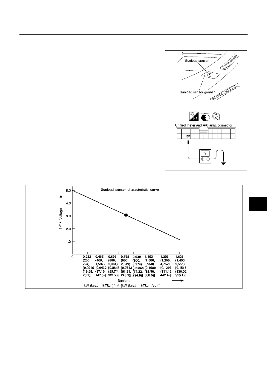
COMPONENT INSPECTION
Sunload Sensor

Measure voltage between unified meter and A/C amp. harness con-
nector M51 terminal 50 (O) and ground.
If NG, replace sunload sensor.

When checking sunload sensor, select a place where sun shines directly on it.

RJIA1807E

SHA930E

ATC-124

TROUBLE DIAGNOSIS

Revision; 2004 April

2003 Murano

Intake Sensor Circuit

AJS00114

COMPONENT DESCRIPTION
Intake Sensor

The intake sensor is located on the heater & cooling unit. It converts
temperature of air after it passes through the evaporator into a resis-
tance value which is then input to the unified meter and A/C amp.

DIAGNOSTIC PROCEDURE FOR INTAKE SENSOR

SYMPTOM: Intake sensor circuit is open or shorted. (24 or 

24 is

indicated on unified meter and A/C amp. as a result of performing
Self-diagnosis STEP-2.)

1. 

CHECK VOLTAGE BETWEEN INTAKE SENSOR AND GROUND

1.

Disconnect intake sensor connector.

2.

Turn ignition switch ON.

3.

Check voltage between intake sensor harness connector M256
terminal 1 (R/W) and ground.

OK or NG

OK

>> GO TO 2.

NG

>> GO TO 4.

2. 

CHECK CIRCUIT CONTINUITY BETWEEN INTAKE SENSOR AND UNIFIED METER AND A/C AMP.

1.

Turn ignition switch OFF.

2.

Disconnect unified meter and A/C amp. connector.

3.

Check continuity between intake sensor harness connector
M256 terminal 2 (B/Y) and unified meter and A/C amp. harness
connector M51 terminal 49 (B/Y).

OK or NG

OK

>> GO TO 3.

NG

>> Repair harness or connector.

RJIA1808E

RJIA1458E

1 – Ground

: Approx. 5V

RJIA1809E

2 – 49

: Continuity should exist.

RJIA1810E

TROUBLE DIAGNOSIS

ATC-125

C

D

E

F

G

H

I

K

L

M

A

B

ATC

Revision; 2004 April

2003 Murano

3. 

CHECK INTAKE SENSOR

Refer to 

ATC-125, "Intake Sensor"

 .

OK or NG

OK

>> 1. Replace unified meter and A/C amp.

2. Go to self-diagnosis 

ATC-69, "FUNCTION CONFIRMATION PROCEDURE"

  and perform self-

diagnosis STEP-2. Confirm that code No. 20 is displayed.

NG

>> 1. Replace intake sensor.

2. Go to self-diagnosis 

ATC-69, "FUNCTION CONFIRMATION PROCEDURE"

  and perform self-

diagnosis STEP-2. Confirm that code No. 20 is displayed.

4. 

CHECK CIRCUIT CONTINUITY BETWEEN INTAKE SENSOR AND UNIFIED METER AND A/C AMP.

1.

Turn ignition switch OFF.

2.

Disconnect unified meter and A/C amp. connector.

3.

Check continuity between intake sensor harness connector
M256 terminal 1 (R/W) and unified meter and A/C amp. harness
connector M51 terminal 41 (R/Y).

4.

Check continuity between intake sensor harness connector
M256 terminal 1 (R/W) and ground.

OK or NG

OK

>> 1. Replace unified meter and A/C amp.

2. Go to self-diagnosis 

ATC-69, "FUNCTION CONFIRMATION PROCEDURE"

  and perform self-

diagnosis STEP-2. Confirm that code No. 20 is displayed.

NG

>> Repair harness or connector.

COMPONENT INSPECTION
Intake Sensor

After disconnecting intake sensor connector, measure resistance
between terminals 1 and 2 at sensor harness side, using the table
below.

If NG, replace intake sensor.

1 – 41

: Continuity should exist.

1 – Ground

: Continuity should not exist.

RJIA1811E

Temperature 

°

C (

°

F)

Resistance k

15 (5)

18.63

10 (14)

14.14

5 (23)

10.85

0 (32)

8.40

5 (41)

6.57

10 (50)

5.18

15 (59)

4.12

20 (68)

3.30

25 (77)

2.66

30 (86)

2.16

35 (95)

1.77

40 (104)

1.46

45 (113)

1.21

RJIA1812E

ATC-126

CONTROLLER

Revision; 2004 April

2003 Murano

CONTROLLER

PFP:27500

Removal and Installation of A/C and AV Switch

AJS000ZN

REMOVAL

Refer to 

AV-57, "Removal and Installation for A/C and AV Switch"

 .

INSTALLATION

Installation is basically the reverse order of removal.

AUTO AMP

ATC-127

C

D

E

F

G

H

I

K

L

M

A

B

ATC

Revision; 2004 April

2003 Murano

AUTO AMP

PFP:27760

Removal and Installation of Unified Meter and A/C Amp.

AJS000ZP

REMOVAL

1.

Remove A/C and AV switch from audio unit. Refer to 

AV-57,

"Removal and Installation for A/C and AV Switch"

 .

2.

Remove the fixing screws, then remove the unified meter and A/
C amp.

INSTALLATION

Installation is basically the reverse order of removal.

RJIA1813E

ATC-128

AMBIENT SENSOR

Revision; 2004 April

2003 Murano

AMBIENT SENSOR

PFP:27722

Removal and Installation

AJS000ZR

REMOVAL

1.

Remove ambient sensor from bracket.

2.

Disconnect ambient sensor connector, then remove it.

INSTALLATION

Installation is basically the reverse order of removal.

RJIA1800E

IN-VEHICLE SENSOR

ATC-129

C

D

E

F

G

H

I

K

L

M

A

B

ATC

Revision; 2004 April

2003 Murano

IN-VEHICLE SENSOR

PFP:27720

Removal and Installation

AJS000ZS

REMOVAL

1.

Remove instrument driver lower panel. Refer to 

IP-11, "Removal

and Installation"

 .

2.

Remove in-vehicle sensor.

INSTALLATION

Installation is basically the reverse order of removal.

RJIA1814E

ATC-130

SUNLOAD SENSOR

Revision; 2004 April

2003 Murano

SUNLOAD SENSOR

PFP:27721

Removal and Installation

AJS000ZT

REMOVAL

1.

Remove instrument mask (right side). Refer to 

IP-11, "Removal

and Installation"

 .

2.

Disconnect sunload sensor connector, then remove sunload
sensor.

INSTALLATION

Installation is basically the reverse order of removal.

RJIA1806E

INTAKE SENSOR

ATC-131

C

D

E

F

G

H

I

K

L

M

A

B

ATC

Revision; 2004 April

2003 Murano

INTAKE SENSOR

PFP:27723

Removal and Installation

AJS000ZU

REMOVAL

1.

Set the temperature at 18

°

C (60

°

F), and then disconnect the battery negative cable. 

2.

Use a refrigerant collecting equipment (for HFC-134a) to discharge refrigerant.

3.

Remove cowl top cover. Refer to 

EI-21, "COWL TOP"

 .

4.

Remove high-pressure pipe 1 fixing clip.

5.

Remove low-pressure flexible hose fixing bolt.

6.

Disconnect evaporator-side one-touch joints. 

a.

Set a disconnector (High-pressure side: 92530-89908, Low-
pressure side: 92530-89916) on A/C piping.

b.

Slide a disconnector toward vehicle front until it clicks.

c.

Slide A/C piping toward vehicle front and disconnect it.

CAUTION:

Seal connection opening of piping with a cap or vinyl tape
to avoid exposure to atmosphere.

7.

Remove blower unit. Refer to 

ATC-133, "BLOWER UNIT"

 .

8.

Remove air mix door motor (Passenger side).

9.

Remove intake sensor connector, foot duct and heater core
cover.

10. Remove evaporator cover from heater & cooling unit.

11. Remove the fixing bolt, then remove the low-pressure pipe 2

and high-pressure pipe 2.

CAUTION:

Seal connection opening of piping with a cap or vinyl tape
to avoid exposure to atmosphere.

12. Slide the evaporator to passenger side, then remove the intake

sensor.

RJIA1815E

RJIA1816E

RJIA1817E

RJIA1808E

ATC-132

INTAKE SENSOR

Revision; 2004 April

2003 Murano

INSTALLATION

Installation is basically the reverse order of removal.

CAUTION:

Replace O-rings for A/C piping with new ones. Before installing, apply compressor oil to them.

Connection point for female-side piping is thin. So, when inserting male-side piping, take care not
to deform female-side piping. Slowly insert in axial direction.

Insert one-touch joint connection point securely until it clicks.

After piping has been connected, pull male-side piping by hand to make sure piping does not
come off.

BLOWER UNIT

ATC-133

C

D

E

F

G

H

I

K

L

M

A

B

ATC

Revision; 2004 April

2003 Murano

BLOWER UNIT

PFP:27200

Removal and Installation

AJS000ZV

REMOVAL

1.

Remove instrument passenger lower panel. Refer to 

IP-11,

"Removal and Installation"

 .

2.

Remove ECM with bracket attached.

3.

Remove fixing nuts (2), then fixing bolts (2) and screw (1), then
remove blower unit.

CAUTION:

Move blower unit rightward, and remove locating pin (1)
and joint. Then remove blower unit downward.

4.

Disconnect intake door motor connector and blower fan motor
connector.

5.

Remove harness clips (2) from blower unit.

6.

Remove blower unit.

INSTALLATION

Installation is basically the reverse order of removal.

CAUTION:

Make sure locating pin (1) and joint are securely inserted.

RJIA1818E

RJIA1819E

ATC-134

BLOWER UNIT

Revision; 2004 April

2003 Murano

Disassembly and Assembly

AJS000ZW

CAUTION:

If retaining tabs are damaged while disassembling blower unit,
use 7 screws (27111-2Y000) to assemble blower unit.

1.

Intake adapter

2.

Intake box case

3.

Intake upper case

4.

Intake lower case

5.

Blower fan motor assembly

6.

Intake door motor

7.

In-cabin microfilter

8.

Filter cover

9.

Intake door 2

10. Intake door 1

11.

Intake door lever 1

12. Intake door link

13. Intake door lever 2

RJIA1820E

RJIA1821E

BLOWER MOTOR

ATC-135

C

D

E

F

G

H

I

K

L

M

A

B

ATC

Revision; 2004 April

2003 Murano

BLOWER MOTOR

PFP:27226

Removal and Installation

AJS000ZX

REMOVAL

1.

Remove instrument passenger lower panel. Refer to 

IP-11,

"Removal and Installation"

 .

2.

Disconnect blower motor connector.

3.

Remove screws from blower motor, then remove it.

INSTALLATION

Installation is basically the reverse order of removal.

RJIA1822E

ATC-136

INTAKE DOOR MOTOR

Revision; 2004 April

2003 Murano

INTAKE DOOR MOTOR

PFP:27730

Removal and Installation

AJS000ZY

REMOVAL

1.

Remove blower unit. Refer to 

ATC-133, "BLOWER UNIT"

 .

2.

Remove intake door motor from the blower unit.

INSTALLATION

Installation is basically the reverse order of removal.

RJIA1823E

IN-CABIN MICROFILTER

ATC-137

C

D

E

F

G

H

I

K

L

M

A

B

ATC

Revision; 2004 April

2003 Murano

IN-CABIN MICROFILTER

PFP:27277

Removal and Installation

AJS000ZZ

FUNCTION

Air inside passenger compartment is kept clean at either recircula-
tion or fresh mode by installing in-cabin microfilter into blower unit.

REPLACEMENT TIMING

Replace in-cabin microfilter.
Refer to 

MA-8, "CHASSIS AND BODY MAINTENANCE"

  in SCHEDULE 1 and 

MA-9, "CHASSIS AND BODY

MAINTENANCE"

  in SCHEDULE 2.

Caution label is fixed inside the glove box.

REPLACEMENT PROCEDURES

1.

Remove the instrument passenger lower panel. Refer to 

IP-11,

"Removal and Installation"

 .

2.

Remove the filter cover, then remove the in-cabin microfilter.

3.

Take out the in-cabin microfilter from blower unit.

4.

Replace with new one and reinstall on blower unit.

5.

Reinstall the glove box.

RJIA1331E

RJIA1824E

ATC-138

HEATER & COOLING UNIT ASSEMBLY

Revision; 2004 April

2003 Murano

HEATER & COOLING UNIT ASSEMBLY

PFP:27110

Removal and Installation

AJS00100

REMOVAL

1.

Use a refrigerant collecting equipment (for HFC-134a) to discharge refrigerant.

2.

Drain coolant from cooling system. Refer to 

CO-8, "Changing Engine Coolant"

 .

3.

Remove cowl top cover. Refer to 

EI-21, "COWL TOP"

 .

4.

Disconnect evaporator-side one-touch joints.

a.

Set a disconnector (High-pressure side: 92530-89908, Low-
pressure side: 92530-89916) on A/C piping.

b.

Slide a disconnector toward vehicle front until it clicks.

c.

Slide A/C piping toward vehicle front and disconnect it.

CAUTION:

Seal connection opening of piping with a cap or vinyl tape
to avoid exposure to atmosphere.

5.

Disconnect two heater hoses from heater core.

6.

Remove instrument panel assembly. Refer to 

IP-11, "Removal

and Installation"

 .

7.

Remove blower unit. Refer to 

ATC-133, "BLOWER UNIT"

 .

8.

Remove clips of vehicle harness from steering member.

9.

Remove instrument stays (driver side and passenger side).

10. Renove rear ventilator duct1 and front floor duct. Refer to 

ATC-

147, "Removal of Rear Ventilator Ducts"

  and 

ATC-148,

"Removal of Floor Ducts"

 .

RJIA1815E

RJIA1825E

RJIA1826E


Content      ..     8      9      10      11     ..