Nissan Murano Z51 (2008 year). Manual - part 400
WCS-92
< ECU DIAGNOSIS >
BCM (BODY CONTROL MODULE)
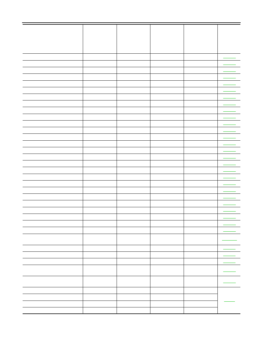
B2555: STOP LAMP
—
×
—
—
B2556: PUSH-BTN IGN SW
—
×
×
—
B2557: VEHICLE SPEED
×
×
×
—
B2560: STARTER CONT RELAY
×
×
×
—
B2562: LOW VOLTAGE
—
×
—
—
B2601: SHIFT POSITION
×
×
×
—
B2602: SHIFT POSITION
×
×
×
—
B2603: SHIFT POSI STATUS
×
×
×
—
B2604: PNP SW
×
×
×
—
B2605: PNP SW
×
×
×
—
B2606: S/L RELAY
×
×
×
—
B2607: S/L RELAY
×
×
×
—
B2608: STARTER RELAY
×
×
×
—
B2609: S/L STATUS
×
×
×
—
B260A: IGNITION RELAY
×
×
×
—
B260B: STEERING LOCK UNIT
—
×
×
—
B260C: STEERING LOCK UNIT
—
×
×
—
B260D: STEERING LOCK UNIT
—
×
×
—
B260F: ENG STATE SIG LOST
×
×
×
—
B2612: S/L STATUS
×
×
×
—
B2614: ACC RELAY CIRC
—
×
×
—
B2615: BLOWER RELAY CIRC
—
×
×
—
B2616: IGN RELAY CIRC
—
×
×
—
B2617: STARTER RELAY CIRC
×
×
×
—
B2618: BCM
×
×
×
—
B2619: BCM
×
×
×
—
B261A: PUSH-BTN IGN SW
—
×
×
—
B261E: VEHICLE TYPE
×
×
×
(Turn ON for 15
seconds)
—
B2621: INSIDE ANTENNA
—
×
—
—
B2622: INSIDE ANTENNA
—
×
—
—
B2623: INSIDE ANTENNA
—
×
—
—
B26E9: S/L STATUS
×
×
×
(Turn ON for 15
seconds)
—
B26EA: KEY REGISTRATION
—
×
×
(Turn ON for 15
seconds)
—
C1704: LOW PRESSURE FL
—
—
—
×
C1705: LOW PRESSURE FR
—
—
—
×
C1706: LOW PRESSURE RR
—
—
—
×
C1707: LOW PRESSURE RL
—
—
—
×
CONSULT display
Fail-safe
Freeze Frame
Data
•Vehicle Speed
•Odo/Trip Meter
•Vehicle Condi-
tion
Intelligent Key
warning lamp ON
Tire pressure
monitor warning
lamp ON
Reference
page
Revision: 2008 October
2009 Murano