Nissan Murano Z51 (2008 year). Manual - part 387
 

  Index      Manuals     Nissan Murano Z51 (2008 year) - Service and Repair Manual


Search            copyright infringement  


Content      ..     385      386      387      388     ..


Nissan Murano Z51 (2008 year). Manual - part 387


VTL-12

< PRECAUTION >

[WITHOUT 7 INCH DISPLAY]

PRECAUTIONS

• Perform leakage test and check that there is no leakage from connections after connecting the line.

Disconnect the line and replace the O-ring when the refrigerant leakage point is found. Then tighten
the connections of seal seat to the specified torque.

Service Equipment

INFOID:0000000003072881

RECOVERY/RECYCLING EQUIPMENT

Be certain to follow the manufacturer instructions for machine operation and machine maintenance. Never
introduce any refrigerant other than that specified into the machine.

ELECTRICAL LEAK DETECTOR

Be certain to follow the manufacturer instructions for tester operation and tester maintenance.

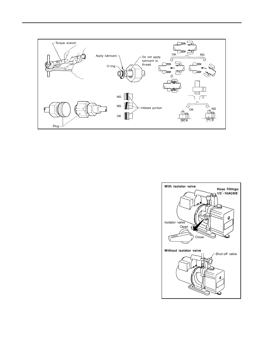
VACUUM PUMP

The lubricant contained inside the vacuum pump is not compatible
with the specified lubricant for HFC-134a (R-134a) A/C systems.
The vent side of the vacuum pump is exposed to atmospheric pres-
sure. So the vacuum pump lubricant may migrate out of the pump
into the service hose. This is possible when the pump is switched
OFF after evacuation (vacuuming) and the hose is connected to it.
To prevent this migration, use a manual valve placed near the hose-
to-pump connection, as per the following procedure.
• Vacuum pumps usually have a manual isolator valve as part of the

pump. Close this valve to isolate the service hose from the pump.

• Use a hose equipped with a manual shut-off valve near the pump

end for pumps without an isolator. Close the valve to isolate the
hose from the pump.

• Disconnect the hose from the pump if the hose has an automatic

shut-off valve. As long as the hose is connected, the valve is open
and lubricating oil may migrate.

Some one-way valves open when vacuum is applied and close
under the no vacuum condition. Such valves may restrict the ability
of the pump to create a deep vacuum and are not recommended.

MANIFOLD GAUGE SET

RHA861F

RHA270DA

Revision: 2008 October

2009 Murano

PRECAUTIONS

VTL-13

< PRECAUTION >

[WITHOUT 7 INCH DISPLAY]

C

D

E

F

G

H

J

K

L

M

A

B

VTL

N

O

P

Be certain that the gauge face indicates HFC-134a or R-134a. Be
sure the gauge set has 1/2

-16 ACME threaded connections for ser-

vice hoses. Confirm the set has been used only with refrigerant
HFC-134a (R-134a) and specified lubricants.

SERVICE HOSES

Be certain that the service hoses display the markings described
(colored hose with a black stripe). All hoses must equip positive
shut-off devices (either manual or automatic) near the end of the
hoses opposite to the manifold gauge.

SERVICE COUPLERS

Never attempt to connect HFC-134a (R-134a) service couplers to a
CFC-12 (R-12) A/C system. The HFC-134a (R-134a) couplers do
not properly connect to the CFC-12 (R-12) system. However, if an
improper connection is attempted, discharging and contamination
may occur.

REFRIGERANT WEIGHT SCALE

Verify that no refrigerant other than HFC-134a (R-134a) and speci-
fied lubricants have been used with the scale. The hose fitting must
be 1/2

-16 ACME if the scale controls refrigerant flow electronically.

CHARGING CYLINDER

Use of a charging cylinder is not recommended. Refrigerant may be vented into the air from the top valve of
the cylinder when filling the cylinder with refrigerant. Also, the accuracy of the cylinder is generally less than
that of an electronic scale or of quality recycle/recharge equipment.

SHA533D

RHA272D

Shut-off valve rotation

A/C service valve

Clockwise

Open

Counterclockwise

Close

RHA273D

RHA274D

Revision: 2008 October

2009 Murano

VTL-14

< PRECAUTION >

[WITHOUT 7 INCH DISPLAY]

COMPRESSOR

COMPRESSOR

General Precautions

INFOID:0000000003072882

CAUTION:

• Plug all openings to prevent moisture and foreign material from entering.
• Store it in the same way as it is when mounted on the car when the compressor is removed.
• Follow “Maintenance of Lubricant Quantity in Compressor” exactly when replacing or repairing

compressor. Refer to 

HA-25, "Maintenance of Lubricant Quantity"

.

• Keep friction surfaces between clutch and pulley clean. Wipe it off by using a waste moistened with

thinner if the surface is contaminated with lubricant.

• Turn the compressor shaft by hand more than five turns in both directions after compressor service

operation. This equally distributes lubricant inside the compressor. Let the engine idle and operate
the compressor for one hour after the compressor is installed.

• Apply voltage to the new compressor and check for normal operation after replacing the compressor

magnet clutch.

Revision: 2008 October

2009 Murano

FLUORESCENT LEAK DETECTOR

VTL-15

< PRECAUTION >

[WITHOUT 7 INCH DISPLAY]

C

D

E

F

G

H

J

K

L

M

A

B

VTL

N

O

P

FLUORESCENT LEAK DETECTOR

General Precautions

INFOID:0000000003072883

CAUTION:

• The A/C system contains a fluorescent leak detection dye used for locating refrigerant leakages. An

ultraviolet (UV) lamp is required to illuminate the dye when inspecting for leakages.

• Always wear fluorescence enhancing UV safety goggles to protect eyes and enhance the visibility of

the fluorescent dye.

• The fluorescent dye leak detector is not a replacement for an electrical leak detector (SST: J-41995).

The fluorescent dye leak detector should be used in conjunction with an electrical leak detector
(SST: J-41995) to pin-point refrigerant leakages.

• Read and follow all manufacturer operating instructions and precautions prior to performing work

for safety and customer satisfaction.

• A compressor shaft seal should not necessarily be repaired because of dye seepage. The compres-

sor shaft seal should only be repaired after confirming the leakage with an electrical leak detector
(SST: J-41995).

• Always remove any remaining dye from the leakage area after repairs are completed to avoid a mis-

diagnosis during future service.

• Never allow dye to come into contact with painted body panels or interior components. Immediately

clean with the approved dye cleaner if dye is spilled. Fluorescent dye left on a surface for an
extended period of time cannot be removed.

• Never spray fluorescent dye cleaning agent on hot surfaces (engine exhaust manifold, etc.).
• Never use more than one refrigerant dye bottle [1/4 ounce (7.4 cc)] per A/C system.
• Leak detection dyes for HFC-134a (R-134a) and CFC-12 (R-12) A/C systems are different. Never use

HFC-134a (R-134a) leak detection dye in CFC-12 (R-12) A/C system or CFC-12 (R-12) leak detection
dye in HFC-134a (R-134a) A/C system, otherwise A/C system damage may result.

• The fluorescent properties of the dye remains for three or more years unless a compressor malfunc-

tion occurs.

IDENTIFICATION

NOTE:
Vehicles with factory installed fluorescent dye have a green label.
Vehicles without factory installed fluorescent dye have a blue label.

IDENTIFICATION LABEL FOR VEHICLE

Vehicles with factory installed fluorescent dye have an identification label on the front side of hood.

Revision: 2008 October

2009 Murano

VTL-16

< PREPARATION >

[WITHOUT 7 INCH DISPLAY]

PREPARATION

PREPARATION

PREPARATION

Special Service Tool

INFOID:0000000003072884

The actual shapes of Kent-Moore tools may differ from those of special service tools illustrated here.

HFC-134a (R-134a) Service Tool and Equipment

• Never mix HFC-134a (R-134a) refrigerant and/or its specified lubricant with CFC-12 (R-12) refrigerant and/

or its lubricant.

• Separate and non-interchangeable service equipment must be used for handling each type of refrigerant/

lubricant.

• Refrigerant container fittings, service hose fittings and service equipment fittings (equipment that handles

refrigerant and/or lubricant) are different between CFC-12 (R-12) and HFC-134a (R-134a). This is to avoid
mixed use of the refrigerants/lubricant.

• Never use adapters that convert one size fitting to another. Refrigerant/lubricant contamination occurs and

compressor malfunction may result.

Tool number

(Kent-Moore No.)

Tool name

Description

(ACR2005-NI)
ACR5 A/C Service Center

Function: Refrigerant recovery, recycling 
and recharging

(J-41995)
Electrical leak detector

Power supply:
DC 12 V (Battery terminal)

(J-43926)
Refrigerant dye leak detection 
kit
Kit includes:
(J-42220)
UV lamp and UV safety goggles
(J-41459)
HFC-134a (R-134a) dye injector
Use with J-41447, 1/4 ounce 
bottle
(J-41447)
HFC-134a (R-134a) fluorescent 
leak detection dye
(Box of 24, 1/4 ounce bottles)
(J-43872) 
Refrigerant dye cleaner

Power supply:
DC 12 V (Battery terminal)

WJIA0293E

AHA281A

ZHA200H

Revision: 2008 October

2009 Murano

PREPARATION

VTL-17

< PREPARATION >

[WITHOUT 7 INCH DISPLAY]

C

D

E

F

G

H

J

K

L

M

A

B

VTL

N

O

P

(J-42220)
 UV lamp and UV safety goggles

Power supply:
DC 12 V (Battery terminal)
For checking refrigerant leakage when flu-
orescent dye is equipped in A/C system
Includes:
UV lamp and UV safety goggles

(J-41447)
HFC-134a (R-134a) fluorescent 
leak detection dye
(Box of 24, 1/4 ounce bottles)

Application:
For HFC-134a (R-134a) PAG oil
Container:
1/4 ounce (7.4 cc) bottle
(Includes self-adhesive dye identification 
labels for affixing to vehicle after charging 
system with dye.)

(J-41459)
HFC-134a (R-134a) dye injector
Use with J-41447, 1/4 ounce 
bottle

For injecting 1/4 ounce of fluorescent leak 
detection dye into A/C system

(J-43872)
Refrigerant dye cleaner

For cleaning dye spills

(J-39183)
Manifold gauge set (with hoses 
and couplers)

Identification:
• The gauge face indicates HFC-134a (R-

134a).

Fitting size: Thread size

• 1/2

-16 ACME

Service hoses
• High-pressure side hose

(J-39501-72)

• Low-pressure side hose

(J-39502-72)

• Utility hose

(J-39476-72)

Hose color:
• Low-pressure side hose: Blue with black 

stripe

• High-pressure side hose: Red with black 

stripe

• Utility hose: Yellow with black stripe or 

green with black stripe

Hose fitting to gauge:

• 1/2

-16 ACME

Tool number

(Kent-Moore No.)

Tool name

Description

SHA438F

SHA439F

SHA440F

SHA441F

RJIA0196E

S-NT201

Revision: 2008 October

2009 Murano

VTL-18

< PREPARATION >

[WITHOUT 7 INCH DISPLAY]

PREPARATION

Commercial Service Tool

INFOID:0000000003072885

Service couplers
• High-pressure side coupler

(J-39500-20)

• Low-pressure side coupler

(J-39500-24)

Hose fitting to service hose:
M14 x 1.5 fitting is optional or permanently 
attached.

(J-39650)
Refrigerant weight scale

For measuring of refrigerant
Fitting size: Thread size

1/2

-16 ACME

(J-39649)
Vacuum pump
(Including the isolator valve)

Capacity:
• Air displacement: 4 CFM
• Micron rating: 20 microns
• Oil capacity: 482 g (17 oz.)
Fitting size: Thread size

• 1/2

-16 ACME

Tool number

(Kent-Moore No.)

Tool name

Description

S-NT202

S-NT200

S-NT203

Tool name

Description

Refrigerant identifier equipment

Checking for refrigerant purity and 
system contamination

Power tools

For loosening bolts and nuts

Remover tools

Remove clips, pawls, metal clips

RJIA0197E

PBIC0190E

PIIB7923J

Revision: 2008 October

2009 Murano

PREPARATION

VTL-19

< PREPARATION >

[WITHOUT 7 INCH DISPLAY]

C

D

E

F

G

H

J

K

L

M

A

B

VTL

N

O

P

Sealant or/and Lubricant

INFOID:0000000003072886

HFC-134a (R-134a) Service Tool and Equipment

• Never mix HFC-134a (R-134a) refrigerant and/or its specified lubricant with CFC-12 (R-12) refrigerant and/

or its lubricant.

• Separate and non-interchangeable service equipment must be used for handling each type of refrigerant/

lubricant.

• Refrigerant container fittings, service hose fittings and service equipment fittings (equipment that handles

refrigerant and/or lubricant) are different between CFC-12 (R-12) and HFC-134a (R-134a). This is to avoid
mixed use of the refrigerants/lubricant.

• Never use adapters that convert one size fitting to another. Refrigerant/lubricant contamination occurs and

compressor malfunction may result.

Tool name

Description

HFC-134a (R-134a) refrigerant

Container color: Light blue
Container marking: HFC-134a (R-
134a)
Fitting size: Thread size

• Large container 1/2

-16 ACME

NISSAN A/C System Oil Type S 
(DH-PS)

Type: Polyalkylene glycol oil (PAG), 
type S (DH-PS)
Application:
HFC-134a (R-134a) swash plate com-
pressors (NISSAN only)

Capacity: 40 m

 (1.4 US fl oz., 1.4 

Imp fl oz.) 

S-NT196

S-NT197

Revision: 2008 October

2009 Murano

VTL-20

< ON-VEHICLE MAINTENANCE >

[WITHOUT 7 INCH DISPLAY]

IN-CABIN MICROFILTER

ON-VEHICLE MAINTENANCE

IN-CABIN MICROFILTER

Exploded View

INFOID:0000000004676921

Removal and Installation

INFOID:0000000003072888

REMOVAL

1.

Remove the filter cover (1), and then remove the in-cabin micro-
filter (2). 

INSTALLATION

Install in the reverse order of removal.

CAUTION:

• If the filter is deformed/damaged when removing, replace it with a new one. Deformed/damaged fil-

termay deteriorate the dust collecting performance.

• When installing, handle the filter with extreme care to avoid deforming/damaging.

Replacement

INFOID:0000000003072889

Replace in-cabin microfilter.
Refer to [

MA-8, "FOR NORTH AMERICA : Schedule 1"

 or 

MA-10, "FOR NORTH AMERICA : Schedule 2"

(FOR NORTH AMERICA)] or 

MA-11, "FOR MEXICO : Periodic Maintenance"

 (FOR MEXICO).

Affix a caution label inside the glove box when replacing filter.

1.

Heater & cooling unit assembly

2.

In-cabin microfilter

3.

Filter cover

JPIIA0895ZZ

JPIIA0552ZZ

Revision: 2008 October

2009 Murano

A/C CONTROL

VTL-21

< ON-VEHICLE REPAIR >

[WITHOUT 7 INCH DISPLAY]

C

D

E

F

G

H

J

K

L

M

A

B

VTL

N

O

P

ON-VEHICLE REPAIR

A/C CONTROL

Exploded View

INFOID:0000000003208740

DISASSEMBLY

Removal and Installation

INFOID:0000000003208741

REMOVAL

1.

Remove the instrument stay cover LH. Refer to 

IP-11, "Exploded View"

2.

Remove the instrument stay cover RH. Refer to 

IP-11, "Exploded View"

3.

Remove the mounting screws (A), and then remove the cluster
lid D (1). 

4.

Remove the mounting screws (A), and then remove the A/C
control (1). 

INSTALLATION

1.

Cluster lid D

2.

A/C control

JPIIA0600ZZ

JPIIA0601ZZ

JPIIA0602ZZ

Revision: 2008 October

2009 Murano

VTL-22

< ON-VEHICLE REPAIR >

[WITHOUT 7 INCH DISPLAY]

A/C CONTROL

Install in the reverse order of removal.

Revision: 2008 October

2009 Murano

A/C DISPLAY

VTL-23

< ON-VEHICLE REPAIR >

[WITHOUT 7 INCH DISPLAY]

C

D

E

F

G

H

J

K

L

M

A

B

VTL

N

O

P

A/C DISPLAY

Exploded View

INFOID:0000000003457773

DISASSEMBLY

Removal and Installation

INFOID:0000000003457774

REMOVAL

1.

Remove the central ventilator assembly. Refer to 

IP-11, "Exploded View"

2.

Remove the mounting screws (A), and then remove the mount-
ing bracket (1). 

3.

Remove the mounting screws (A), and then remove the A/C dis-
play (1). 

INSTALLATION

Install in the reverse order of removal.

1.

Bracket

2.

A/C display

3.

CRT filter

4.

AV display

JPIIA0603ZZ

JPIIA0604ZZ

JPIIA0605ZZ

Revision: 2008 October

2009 Murano

VTL-24

< ON-VEHICLE REPAIR >

[WITHOUT 7 INCH DISPLAY]

A/C AUTO AMP.

A/C AUTO AMP.

Exploded View

INFOID:0000000003072892

DISASSEMBLY

Removal and Installation

INFOID:0000000003072893

REMOVAL

1.

Remove the AV control unit. Refer to 

AV-522, "Exploded View"

2.

Remove the mounting screws (A), and then remove the A/C
auto amp. (1). 

INSTALLATION

Install in the reverse order of removal.

JPIIA0553ZZ

1.

AV control unit

2.

Bracket (LH)

3.

A/C auto amp.

4.

Bracket (RH)

JPIIA0554ZZ

Revision: 2008 October

2009 Murano

AMBIENT SENSOR

VTL-25

< ON-VEHICLE REPAIR >

[WITHOUT 7 INCH DISPLAY]

C

D

E

F

G

H

J

K

L

M

A

B

VTL

N

O

P

AMBIENT SENSOR

Exploded View

INFOID:0000000003072894

Removal and Installation

INFOID:0000000003072895

REMOVAL

1.

Disconnect the ambient sensor connector (A), and then remove
the ambient sensor (1). 

INSTALLATION

Install in the reverse order of removal.

1.

Ambient sensor

JPIIA1300ZZ

JPIIA0556ZZ

Revision: 2008 October

2009 Murano

VTL-26

< ON-VEHICLE REPAIR >

[WITHOUT 7 INCH DISPLAY]

IN-VEHICLE SENSOR

IN-VEHICLE SENSOR

Exploded View

INFOID:0000000003072896

Removal and Installation

INFOID:0000000003072897

REMOVAL

1.

Remove the instrument lower panel LH.  Refer to 

IP-11, "Exploded View"

2.

Remove the mounting screw (A), and then remove the in-vehicle
sensor (1). 

INSTALLATION

Install in the reverse order of removal.

1.

In-vehicle sensor

2.

Instrument lower panel LH

JPIIA0557ZZ

JPIIA0558ZZ

Revision: 2008 October

2009 Murano

SUNLOAD SENSOR

VTL-27

< ON-VEHICLE REPAIR >

[WITHOUT 7 INCH DISPLAY]

C

D

E

F

G

H

J

K

L

M

A

B

VTL

N

O

P

SUNLOAD SENSOR

Exploded View

INFOID:0000000003072898

Removal and Installation

INFOID:0000000003072899

REMOVAL

1.

Disconnect the sunload sensor connector, and then remove the
sunload sensor (1). 

INSTALLATION

Install in the reverse order of removal.

1.

Sunload sensor

JPIIA0559ZZ

JPIIA0560ZZ

Revision: 2008 October

2009 Murano


Content      ..     385      386      387      388     ..