Nissan Murano Z51 (2008 year). Manual - part 376
CONTROL SYSTEM
TM-19
< FUNCTION DIAGNOSIS >
[CVT: RE0F09B]
C
E
F
G
H
I
J
K
L
M
A
B
TM
N
O
P
CONTROL SYSTEM
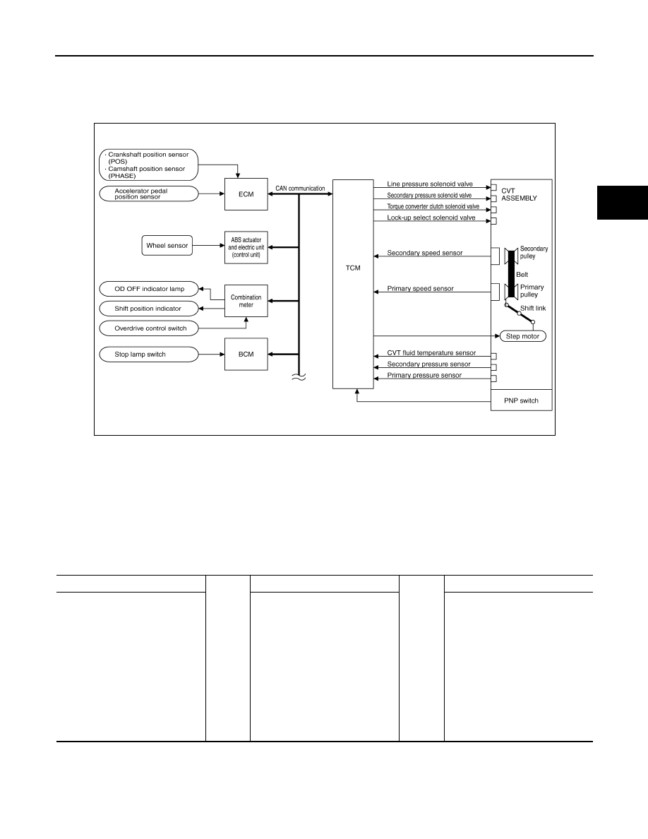
System Diagram
INFOID:0000000003305989
System Description
INFOID:0000000003305990
The CVT senses vehicle operating conditions through various sensors. It always controls the optimum shift
position and reduces shifting and lock-up shocks.
TCM FUNCTION
The function of the TCM is to:
• Receive input signals sent from various switches and sensors.
• Determine required line pressure, shifting point, and lock-up operation.
• Send required output signals to the step motor and the respective solenoids.
INPUT/OUTPUT SIGNAL OF TCM
JPDIA0622GB
SENSORS (or SIGNAL)
⇒
TCM
⇒
ACTUATORS
PNP switch
Accelerator pedal position signal
Closed throttle position signal
Engine speed signal
CVT fluid temperature sensor
Vehicle speed signal
Overdrive control switch signal
Stop lamp switch signal
Primary speed sensor
Secondary speed sensor
Primary pressure sensor
Secondary pressure sensor
Shift control
Line pressure control
Primary pressure control
Secondary pressure control
Lock-up control
Engine brake control
Vehicle speed control
Fail-safe control
Self-diagnosis
CONSULT-III communication line
Duet-EA control
CAN system
On board diagnosis
Step motor
Torque converter clutch solenoid
valve
Lock-up select solenoid valve
Line pressure solenoid valve
Secondary pressure solenoid valve
OD OFF indicator lamp
Shift position indicator
Starter relay
Revision: 2008 October
2009 Murano