Nissan Murano Z51 (2008 year). Manual - part 373
STC-8
< COMPONENT DIAGNOSIS >
POWER STEERING SOLENOID VALVE
YES
>> INSPECTION END
NO
>> Repair or replace damaged parts.
Component Inspection
INFOID:0000000003305952
1.
CHECK POWER STEERING SOLENOID VALVE
1.
Turn the ignition switch OFF.
2.
Disconnect power steering solenoid valve harness connector.
3.
Check resistance between power steering solenoid valve connector terminals.
4.
Check power steering solenoid valve by listening for its operation sound while applying battery voltage to
power steering solenoid valve connector E52 terminals 1 (positive) and 2 (negative).
Is the inspection result normal?
YES
>> INSPECTION END
NO
>> Replace gear-sub assembly. Refer to
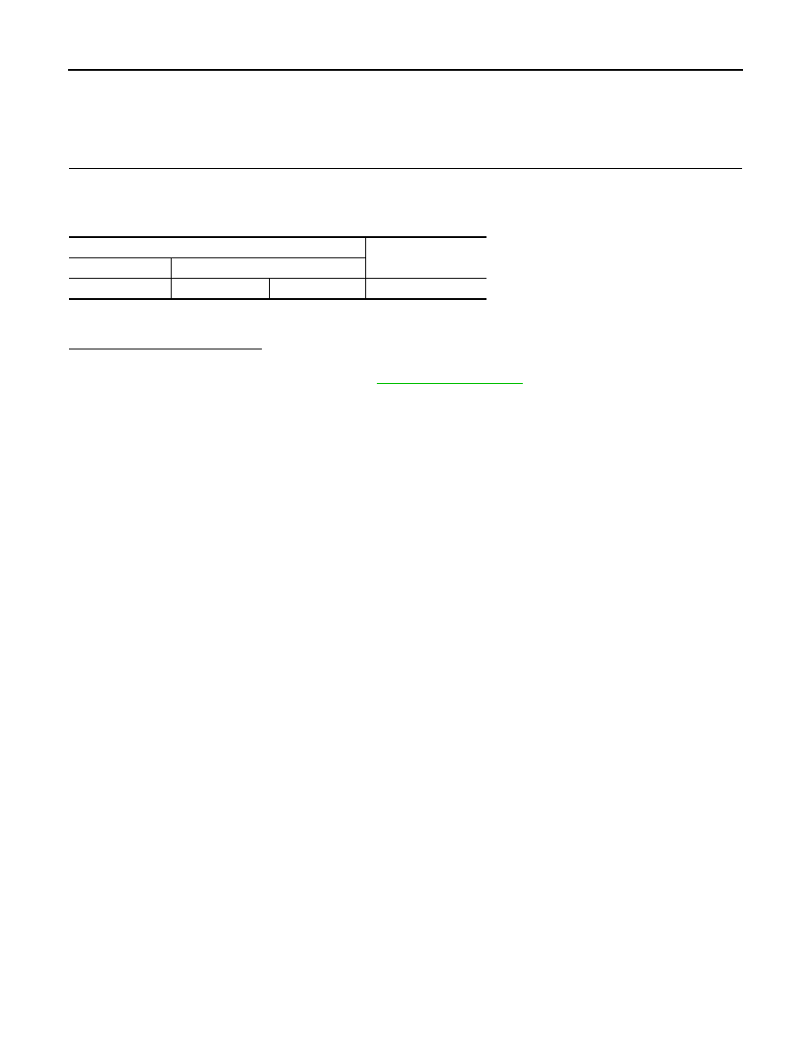
Power steering solenoid valve
Resistance (Approx.)
Connector
Terminal
E52
1 2
4
–
6
Ω
Revision: 2008 October
2009 Murano