Nissan Murano Z51 (2008 year). Manual - part 371


  Index      Manuals     Nissan Murano Z51 (2008 year) - Service and Repair Manual


Search            copyright infringement  


Content      ..     369      370      371      372     ..


Nissan Murano Z51 (2008 year). Manual - part 371


STEERING COLUMN

ST-21

< ON-VEHICLE REPAIR >

C

D

E

F

H

I

J

K

L

M

A

B

ST

N

O

P

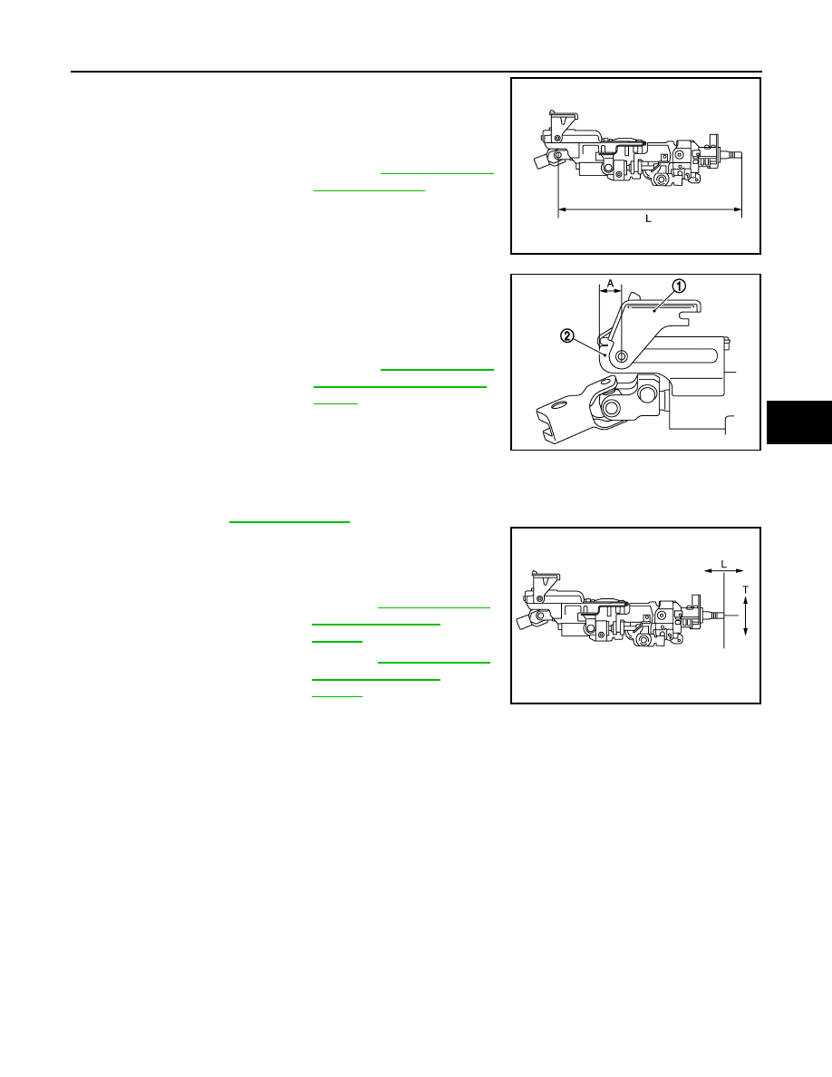
• Measure the length (L) as shown, if vehicle has been involved in a

minor collision. Replace steering column assembly if out side the
standard.

• Install the bracket (1) and steering column housing (2) so that the

clearance (A) is within the specified range as described below.
Replace steering column assembly if out side the standard.

INSPECTION AFTER INSTALLATION

• Check each part of steering column assembly for damage or other malfunctions. Replace if necessary.
• Check the steering wheel play, neutral position steering wheel, steering wheel turning force, and front wheel

turning angle. Refer to 

ST-12, "Inspection"

.

• Check tilt and telescopic mechanism operating range tilt operating

range (L), telescopic operating range (T) as shown in the figure.

Standard

L

: Refer to 

ST-44, "Steering 

Column Length"

.

JSGIA0563ZZ

Standard

A

: Refer to 

ST-44, "Steering 

Column Mounting Dimen-
sions"

.

JSGIA0389ZZ

Standard

T

: Refer to 

ST-44, "Steering 

Column Operating 
Range"

.

L

: Refer to 

ST-44, "Steering 

Column Operating 
Range"

.

JSGIA0309ZZ

Revision: 2008 October

2009 Murano

ST-22

< ON-VEHICLE REPAIR >

LOWER SHAFT

LOWER SHAFT

Exploded View

INFOID:0000000003305906

Removal and Installation

INFOID:0000000003305907

REMOVAL

1.

Set the vehicle to the straight-ahead position.

2.

Fix the steering wheel.

3.

Remove upper joint fixing bolt and nut (lower shaft side).

4.

Separate the lower shaft from the steering gear assembly by
sliding the slide shaft (A: sliding range).

CAUTION:

Spiral cable may be cut if steering wheel turns while sepa-
rating steering column assembly and steering column
assembly. Be sure to secure steering wheel using string to
avoid turning.

5.

Remove the accelerator pedal bracket and lever assembly.
Refer to 

ACC-3, "Exploded View"

.

6.

Remove the side brake pedal bracket and wire clamp stay.

7.

Remove the hole cover mounting nuts.

8.

Remove the hole cover seal, clamp and hole cover.

9.

Remove lower shaft joint fixing bolt (steering gear side).

10. Remove the lower shaft.

INSTALLATION

Note the following, and install in the reverse order of removal.

CAUTION:

Spiral cable may be cut if steering wheel turns while separating steering column assembly and steer-
ing gear assembly. Be sure to secure steering wheel using string to avoid turning.

1.

Steering column assembly

2.

Hole cover seal

3.

Clamp

4.

Hole cover

5.

Lower shaft

Refer to 

GI-4, "Components"

 for symbols in the figure.

JSGIA0311GB

JSGIA0312ZZ

Revision: 2008 October

2009 Murano

LOWER SHAFT

ST-23

< ON-VEHICLE REPAIR >

C

D

E

F

H

I

J

K

L

M

A

B

ST

N

O

P

• Tighten the clamp to the specified torque and check the clamp

length (A).

• After lower shaft (steering gear side) fitted, make sure there is not

gap (A) between the yoke (1), lower shaft (2), joint fixing bolt (3).

• When installing lower joint to steering gear assembly, follow the procedure listed below.
- Set rack of steering gear in the neutral position.

NOTE:
To get the neutral position of rack, turn gear-sub assembly and measure the distance of inner socket, and
then measure the intermediate position of the distance.

- Align rear cover cap projection (A) with the marking position of

gear housing assembly (B).

- Install slit part of lower joint (C) aligning with the rear cover cap

projection (A). Make sure that the slit part of lower joint (C) is
aligned with rear cover cap projection (A) and the marking position
of gear housing assembly (B).

• Adjust neutral position of steering angle sensor. Refer to 

BRC-9,

"ADJUSTMENT OF STEERING ANGLE SENSOR NEUTRAL
POSITION : Special Repair Requirement"

.

• Check the following after installation:
- Check if steering wheel turns smoothly when it is turned several times fully to the end of the left and right.
- Check the steering wheel play, neutral position steering wheel, steering wheel turning force, and front wheel

turning angle. Refer to 

ST-12, "Inspection"

.

Inspection

INFOID:0000000003305908

• Check the length (A) (extended position) of the lower shaft.

• Check each part of lower shaft for damage or other malfunctions.

Replace if there are.

Clamp length “A”

: 14.0 – 18.0 mm (0.551 – 
0.709 in)

JSGIA0094ZZ

JSGIA0180ZZ

: Bolt

JSGIA0313ZZ

Standard

A

: Refer to 

ST-45, "Lower 

Shaft Length"

.

JSGIA0609ZZ

Revision: 2008 October

2009 Murano

ST-24

< ON-VEHICLE REPAIR >

STEERING GEAR AND LINKAGE

STEERING GEAR AND LINKAGE

Exploded View

INFOID:0000000003305917

REMOVAL

2WD models

AWD models

DISASSEMBLY

JSGIA0606GB

1.

Steering gear assembly

2.

Cotter pin

: Vehicle front

Refer to 

GI-4, "Components"

 for symbols in the figure.

JSGIA0607GB

1.

Steering gear assembly

2.

Cotter pin

: Vehicle front

Refer to

GI-4, "Components"

 for symbols in the figure.

Revision: 2008 October

2009 Murano

STEERING GEAR AND LINKAGE

ST-25

< ON-VEHICLE REPAIR >

C

D

E

F

H

I

J

K

L

M

A

B

ST

N

O

P

2WD models

JSGIA0571GB

1.

Low pressure piping

2.

Rear cover cap

3.

Gear-sub assembly

4.

Power steering solenoid valve

5.

O-ring

6.

Adjusting screw

7.

Spring

8.

Retainer

9.

Outer socket

10. Boot clamp

11.

Boot

12. Inner socket

13. Boot clamp (stainless wire)

14. Cylinder tube

15. Gear housing assembly

16. Rack oil seal

17. Rack assembly

18. Rack Teflon ring

19. O-ring

20. End cover assembly

: Apply power steering fluid.

: Apply Genuine Medium Strength Thread Locking Sealant or equivalent. Refer to 

GI-17, "Recommended Chemical Prod-

ucts and Sealants"

.

: Apply Genuine High Performance Thread Sealant or equivalent. Refer to 

GI-17, "Recommended Chemical Products and 

Sealants"

.

: Apply multi-purpose grease.

Refer to 

GI-4, "Components"

 for symbols not described on the above.

Revision: 2008 October

2009 Murano

ST- 26

< ON-VEHICLE REPAIR >

STEERING GEAR AND LINKAGE

AWD models

Removal and Installation

INFOID:0000000003305918

REMOVAL

1.

Set the vehicle to the straight-ahead position.

2.

Remove front road wheel and tires.

3.

Remove splash guards (RH and LH). Refer to 

EXT-23, "FENDER PROTECTOR : Exploded View"

.

4.

Remove engine under cover. Refer to 

EXT-26, "Exploded View"

.

5.

Remove exhaust front tube. Refer to 

EX-5, "Exploded View"

.

6.

Separate the rear propeller shaft (front side). Refer to 

DLN-80, "Exploded View"

 (AWD models). 

7.

Remove heat insulator from front floor. 

JSGIA0572GB

1.

Low pressure piping

2.

Rear cover cap

3.

Gear-sub assembly

4.

Power steering solenoid valve

5.

O-ring

6.

Adjusting screw

7.

Spring

8.

Retainer

9.

Outer socket

10. Boot clamp

11.

Boot

12. Inner socket

13. Boot clamp (stainless wire)

14. Cylinder tube

15. Gear housing assembly

16. Rack oil seal

17. Rack assembly

18. Rack Teflon ring

19. O-ring

20. End cover assembly

: Apply power steering fluid.

: Apply Genuine Medium Strength Thread Locking Sealant or equivalent. Refer to 

GI-17, "Recommended Chemical Prod-

ucts and Sealants"

.

: Apply Genuine High Performance Thread Sealant or equivalent. Refer to 

GI-17, "Recommended Chemical Products and 

Sealants"

.

: Apply multi-purpose grease.

Refer to 

GI-4, "Components"

 for symbols not described on the above.

Revision: 2008 October

2009 Murano

STEERING GEAR AND LINKAGE

ST-27

< ON-VEHICLE REPAIR >

C

D

E

F

H

I

J

K

L

M

A

B

ST

N

O

P

8.

Remove cotter pin (1), and then loosen the nuts.

9.

Remove steering outer socket (2) from steering knuckle (3) so
as not to damage ball joint boot (4) using suitable ball joint
remover.

CAUTION:

Temporarily tighten the nut to prevent damage to threads
and to prevent the ball joint remover from suddenly coming
off.

10. Remove high pressure piping and low pressure hose of hydrau-

lic piping, and then drain power steering fluid.

11. Remove steering hydraulic piping bracket from front steering

gear assembly.

12. Remove power steering solenoid valve harness connector (1)

and harness clip.

13. Remove lower joint fixing bolt (steering gear side).

14. Separate the lower shaft from the steering gear assembly by sliding the slide shaft.

CAUTION:

Spiral cable may be cut if steering wheel turns while separating steering column assembly and
steering gear assembly. Be sure to secure steering wheel using string to avoid turning.

15. Remove the stabilizer assembly. Refer to 

FSU-15, "Exploded View"

.

16. Support front suspension member with a suitable jack.

17. Remove engine mounting insulator (rear) mounting bolt (lower side). Refer to 

EM-68, "2WD : Exploded

View"

 (2WD models), 

EM-77, "AWD : Exploded View"

 (AWD models).

18. Remove engine mounting insulator (LH). Refer to 

EM-68, "2WD : Exploded View"

 (2WD models), 

EM-77,

"AWD : Exploded View"

 (AWD models). 

19. Remove the mounting bolts and nuts of steering gear assembly.
20. Remove member stay, front suspension member fixing bolts and nuts. Refer to 

FSU-17, "Exploded View"

.

21. Lower the suitable jack for the front suspension member to the steering gear assembly can be removed.

INSTALLATION

Note the following, and install in the reverse order of removal.

CAUTION:

Spiral cable may be cut if steering wheel turns while separating steering column assembly and steer-
ing gear assembly. Be sure to secure steering wheel using string to avoid turning.

JSGIA0320ZZ

: Bolt

JSGIA0321ZZ

JSGIA0322ZZ

Revision: 2008 October

2009 Murano

ST-28

< ON-VEHICLE REPAIR >

STEERING GEAR AND LINKAGE

• When installing low pressure hose (1), refer to the figure.

CAUTION:

• Never apply fluid to the hose (1) and tube (2).
• Insert hose securely until it contacts spool (A) of tube.
• Leave clearance (L) when installing clamp (3).

• When installing lower joint to steering gear assembly, follow the procedure listed below.
- Set rack of steering gear in the neutral position.

NOTE:
To get the neutral position of rack, turn gear-sub assembly and measure the distance of inner socket, and
then measure the intermediate position of the distance.

- Align rear cover cap projection (A) with the marking position of

gear housing assembly (B).

- Install slit part of lower joint (C) aligning with the rear cover cap

projection (A). Make sure that the slit part of lower joint (C) is
aligned with rear cover cap projection (A) and the marking position
of gear housing assembly (B).

• After installation, bleed air from the steering hydraulic system.

Refer to 

ST-10, "Inspection"

.

• Perform final tightening of nuts and bolts on each part under

unladen conditions with tires on level ground when removing steer-
ing gear assembly. Check wheel alignment. Refer to 

FSU-9, "Inspection"

.

• Adjust neutral position of steering angle sensor after checking wheel alignment. Refer to 

BRC-9, "ADJUST-

MENT OF STEERING ANGLE SENSOR NEUTRAL POSITION : Special Repair Requirement"

.

Disassembly and Assembly

INFOID:0000000003305919

DISASSEMBLY

1.

Remove low pressure piping.

CAUTION:

• Disassemble and assemble steering gear assembly by fixing the mounting area with a vise using

copper plates.

• Clean steering gear assembly with kerosene before disassembling. Be careful to avoid splash-

ing or applying any kerosene over connector of discharge port or return port.

2.

Remove cylinder tubes from gear housing assembly.

3.

Remove rear cover cap from gear-sub assembly.

4.

Measure adjusting screw height “H”, and loosen adjusting
screw.

CAUTION:

• Never loosen adjusting screw 2 turns or more.
• Replace steering gear assembly if adjusting screw is

loosened 2 turns or more and it is removed.

5.

Remove gear-sub assembly from gear housing assembly.

6.

Remove O-ring from gear housing assembly.

7.

Loosen outer socket lock nut, and remove outer socket.

8.

Remove boot clamps, and then remove boot from inner socket.

CAUTION:

Never damage inner socket and gear housing assembly when removing boot. Inner socket and
gear housing assembly must be replaced if inner socket and gear housing assembly are damaged
because it may cause foreign material interfusion.

Standard

L

: 3 – 8 mm (0.12 – 0.31 in)

JSGIA0118ZZ

: Bolt

JSGIA0111ZZ

SGIA0624E

Revision: 2008 October

2009 Murano

STEERING GEAR AND LINKAGE

ST-29

< ON-VEHICLE REPAIR >

C

D

E

F

H

I

J

K

L

M

A

B

ST

N

O

P

9.

Remove inner socket from gear housing assembly.

10. Drill out the clinching part of gear housing assembly (end cover

assembly side) outer rim with a 3 mm (0.12 in) drill bit. [Drill for
approximately 1.5 mm (0.059 in) depth.]

11. Remove end cover assembly with a 36 mm (1.42 in) open head

(suitable tool).

CAUTION:

Never damage rack assembly surface when removing. Rack
assembly must be replaced if damaged because it may
cause fluid leakage.

12. Pull rack assembly together with rack oil seal (outer side) out

from gear housing assembly.

CAUTION:

Never damage cylinder inner wall when remove rack
assembly. Gear housing assembly must be replaced if dam-
aged because it may cause fluid leakage.

13. Heat rack Teflon ring to approximately 40

°

C (104

°

F) with a

dryer, and remove rack Teflon ring and O-ring from rack assem-
bly.

CAUTION:

Never damage rack assembly. Rack assembly must be
replaced if damaged because it cause fluid leakage.

14. Push rack oil seal inside with a 29 mm (1.14 in) socket and an

extension bar to push out rack oil seal (inner side) from gear
housing assembly.

CAUTION:

Never damage gear housing assembly and cylinder inner
wall. Gear housing assembly must be replaced if damaged
because it may cause fluid leakage.

ASSEMBLY

1.

Apply recommended fluid to O-ring. Put an O-ring into a rack Teflon ring.

CAUTION:

Never reuse O-ring.

STC0013D

SST081B

SGIA0151E

SGIA0179E

Revision: 2008 October

2009 Murano

ST-30

< ON-VEHICLE REPAIR >

STEERING GEAR AND LINKAGE

2.

Heat rack Teflon ring to approximately 40

°

C (104

°

C) with a

dryer. Assemble it to mounting groove of rack assembly.

CAUTION:

Never reuse rack Teflon ring.

3.

Install the rack Teflon ring correcting tool [SST: KV48104400
(

)] from tooth side of rack fit rack Teflon ring on rack.

Compress the with tool.

4.

Apply recommended grease to rack oil seal, and then install
rack oil seal in the following procedure. Then assemble rack
assembly to gear housing assembly.

CAUTION:

• Install rack oil seal in a direction so that the lip of inner oil

seal and the lip of outer oil seal face each other.

• Never damage retainer sliding surface by rack assembly.

Replace gear housing assembly if damaged.

• Never damage gear housing assembly inner wall by rack

assembly. Gear housing assembly must be replaced if
damaged because it may cause fluid leakage.

a.

Wrap an OHP sheet [approximately 70 mm (2.76 in) 

×

 100 mm

(3.94 in)]. Around rack assembly teeth to avoid damaging rack
oil seal (inner). Install rack oil seal over sheet. Then, pull OHP
sheet along with rack oil seal until they pass rack assembly
teeth, and remove OHP sheet.

b.

Insert rack oil seal (inner) (1) into rack assembly piston (2).

c.

Push retainer to adjusting screw side by hand, and move the
rack assembly inside the gear housing assembly so that the
rack oil seal (inner) can be pressed against the gear housing
assembly.

SGIA0153E

SGIA0154E

SGIA0205E

SGIA0157E

JSGIA0323ZZ

Revision: 2008 October

2009 Murano

STEERING GEAR AND LINKAGE

ST-31

< ON-VEHICLE REPAIR >

C

D

E

F

H

I

J

K

L

M

A

B

ST

N

O

P

d.

Wrap an OHP sheet [approximately 70 mm (2.76 in) 

×

 100 mm

(3.94 in)]. Around the edge to avoid damaging rack oil seal
(outer). Install rack oil seal over sheet. Then, pull oil seal along
with OHP sheet until they pass rack edge, and remove OHP
sheet.

e.

Install end cover assembly to rack edge, and move rack oil seal
(outer) until it contacts with gear housing assembly.

5.

Tighten end cover assembly to specified torque using a 36 mm
(1.42 in) open head (suitable tool).

CAUTION:

Never damage rack assembly. Replace it if damaged
because it may cause fluid leakage.

6.

Crimp gear housing assembly at one point using a punch as
shown in the figure so as to prevent end cover assembly from
getting loose after tightening end cover assembly.

7.

Apply recommended fluid to O-ring, and then install O-ring to
gear housing assembly.

8.

Install gear-sub assembly to gear housing assembly.

CAUTION:

In order to protect oil seal from any damage, insert gear-
sub assembly straightly.

9.

Install inner socket to gear housing assembly with the following
procedure.

a.

Apply thread sealant into the thread of inner socket.
Use Genuine Medium Strength Thread Locking Sealant or equivalent. Refer to 

GI-17, "Recom-

mended Chemical Products and Sealants"

.

b.

Screw inner socket into rack part and tighten at the specified torque.

10. Decide on the neutral position of the rack stroke (L).

11. Install rear cover cap to gear sub-assembly.

CAUTION:

Make sure that the projection of rear cover cap is aligned
with the marking position of gear housing assembly.

SGIA0157E

SST081B

Standard

L

: Refer to 

ST-45, "Rack 

Stroke"

.

SGIA0871E

SGIA0877E

Revision: 2008 October

2009 Murano

ST-32

< ON-VEHICLE REPAIR >

STEERING GEAR AND LINKAGE

12. Apply recommended thread locking sealant to the thread (2

turns thread), and then screw in the adjusting screw until it
reaches height “H” from gear housing assembly measured
before disassembling.
Use Genuine High Performance Thread Sealant or equiva-
lent. Refer to 

GI-17, "Recommended Chemical Products and

Sealants"

.

13. Move rack assembly 10 strokes throughout the full stroke so that

the parts can fit with each other.

14. Adjust pinion rotating torque with the following procedure.
a.

Measure pinion rotating torque within 

±

180

°

 of neutral position

of the rack assembly using Tools. Stop the gear at the point
where highest torque is read.

b.

Loosen adjusting screw and retighten to 5.4 N·m (0.55 kg-m, 48
in-lb), and then loosen by 20 to 40

°

.

c.

Measure pinion rotating torque using Tools to make sure that the
measured value is within the standard. Readjust if the value is
outside the standard. Replace steering gear assembly, if the
value is outside the standard after readjusting, or adjusting
screw rotating torque is 5 N·m (0.51 kg-m, 44 in-lb) or less.

d.

Apply recommended liquid gasket to inner socket and turn pinion fully to left with inner socket installed to
gear housing assembly.

e.

Install dial gauge at 5 mm (0.20 in) (L) from the edge of gear
housing assembly (1), and tooth point.

f.

Measure vertical movement of rack assembly when pinion is
turned clockwise with torque of 19.6 N·m (2.0 kg-m, 14 ft-lb).
Readjust adjusting screw angle if the measured value is outside
the standard.

• If reading is outside of the specification, readjust screw angle

with adjusting screw.

CAUTION:

• If reading is still outside of specification, or if the rotating torque of adjusting screw is less

than 5 N·m (0.51 kg-m, 44 in-lb), replace steering gear assembly.

• Never turn adjusting screw more than twice.
• Replace steering gear assembly when adjusting screw is removed or turned more than twice.

SGIA0624E

A: Preload gauge [SST: ST3127S000 (J-25765-A)]

B: Preload adapter [SST: KV48103400 (

)]

SGIA1383E

Pinion rotating torque

Around neutral position 
(within

±

100

°

) average (A)

: 1.59 – 2.0 N·m (0.17 – 
0.20 kg-m, 14 – 17 in-lb)

Maximum variation (B)

: 0.39 N·m (0.04 kg-m, 3.0 
in-lb)

Vertical movement

: 0.265 mm (0.0104 in)

SGIA0936E

JSGIA0104ZZ

Revision: 2008 October

2009 Murano

STEERING GEAR AND LINKAGE

ST-33

< ON-VEHICLE REPAIR >

C

D

E

F

H

I

J

K

L

M

A

B

ST

N

O

P

15. Install large end of boot to gear housing assembly.

16. Install small end of boot to inner socket boot mounting groove.
17. Install boot clamp to boot small end.

18. Install boot clamp to the large side of boot with the following procedure.

CAUTION:

Never reuse boot clamp.

a.

Tighten large side of boot with boot clamp (stainless wire).

b.

Wrap clamp around boot groove for two turns. Insert a flat-
bladed screwdriver in loops on both ends of wire. Twist 4 to 4.5
turns while pulling them with force of approximately 98 N (10 kg,
22 lb).

c.

Twist boot clamp as shown. Pay attention to relationship
between winding and twisting directions.

d.

Twisted area (A) of clamp is in the opposite side of adjusting
screw (1) as shown in the figure (to prevent contact with other
parts).

SGIA1325E

Wire length (L)

: 370 mm (14.57 in)

SGIA0163E

SGIA0164E

JSGIA0324ZZ

Revision: 2008 October

2009 Murano

ST-34

< ON-VEHICLE REPAIR >

STEERING GEAR AND LINKAGE

e.

Bent cut end of the wire toward rack axial as shown in the figure
after twisting the wire 4 to 4.5 turns so that cut end does not con-
tact with boot.

19. Install cylinder tubes to gear housing assembly.

20. Install low pressure piping.

21. Adjust inner socket to standard length (L), and then tighten lock

nut to the specified torque. Check length again after tightening
lock nut.

CAUTION:

Adjust toe-in after this procedure. The length achieved after
toe-in adjustment is not necessary the above value.

Inspection

INFOID:0000000003305920

INSPECTION AFTER DISASSEMBLY

Boot

Check boot for cracks, and replace it if a malfunction is detected.

Rack Assembly

Check rack for damage or wear, and replace it if a malfunction is detected.

Gear-Sub Assembly

• Check gear-sub assembly for damage or wear, and replace it if a malfunction is detected.
• Rotate gear-sub assembly and check for torque variation or rattle, and replace it if a malfunction is detected.

Gear Housing Assembly

Check gear housing assembly for damage and scratches (inner wall). Replace if there are.

Outer Socket and Inner Socket

Check the following items and replace the component if it does not meet the standard.

BALL JOINT SWINGING TORQUE

Hook a spring balance at the point shown in the figure and pull the
spring balance. Make sure that the spring balance reads the speci-
fied value when ball stud and inner socket start to move. Replace
outer socket and inner socket if they are outside the standard.

A

: Gear housing RHD side

B

: Gear housing LHD side

JSGIA0325ZZ

Standard

L

: Refer to 

ST-45, "Inner 

Socket Length"

.

SGIA0167E

Standard

(Measuring point of outer socket: Stud cotter pin 
mounting hole)

Outer socket

: Refer to 

ST-45, "Socket 

Swing Force and Rotating 
Torque"

.

SGIA0896E

Revision: 2008 October

2009 Murano

STEERING GEAR AND LINKAGE

ST-35

< ON-VEHICLE REPAIR >

C

D

E

F

H

I

J

K

L

M

A

B

ST

N

O

P

BALL JOINT ROTATING TORQUE

Make sure that the reading is within the following specified range
using preload gauge (A) [SST: ST3127S000 (J-25765-A)]. Replace
outer socket if the reading is outside the specified value.

BALL JOINT AXIAL END PLAY

Apply an axial load of 490 N (50 kg, 110 lb) to ball stud. Using a dial
gauge, measure amount of stud movement, and then make sure that
the value is within the following specified range. Replace outer
socket (1) and inner socket (2) if the measured value is outside the
standard.

INSPECTION AFTER INSTALLATION

• Check if steering wheel turns smoothly when it is turned several times fully to the end of the left and right.
• Check the steering wheel play, neutral position steering wheel, steering wheel turning force, and front wheel

turning angle. Refer to 

ST-12, "Inspection"

.

• Check the fluid level, fluid leakage, and air bleeding hydraulic system. Refer to 

ST-10, "Inspection"

.

Standard 

(Measuring point of inner socket: “*” mark shown in 
the figure)

Inner socket

Refer to 

ST-45, "Socket 

Swing Force and Rotating 
Torque"

.

Standard

Rotating torque

: Refer to 

ST-45, "Socket 

Swing Force and Rotating 
Torque"

.

SGIA1382E

Standard

Outer socket

Refer to 

ST-45, "Socket Axial 

End Play"

.

Inner socket

: Refer to 

ST-45, "Socket Axial 

End Play"

.

JSGIA0109ZZ

Revision: 2008 October

2009 Murano

ST-36

< ON-VEHICLE REPAIR >

POWER STEERING OIL PUMP

POWER STEERING OIL PUMP

Exploded View

INFOID:0000000003305921

REMOVAL

DISASSEMBLY

1.

Power steering oil pump

: Vehicle front

Refer to 

GI-4, "Components"

 for symbols in the figure.

JSGIA0326GB

1.

Pulley

2.

Oil seal

3.

Front bracket

4.

Suction pipe

5.

O-ring 

6.

Body assembly 

7.

Flow control valve spring

8.

Flow control valve 

9.

Flow control valve sub assembly

JSGIA0327GB

Revision: 2008 October

2009 Murano


Content      ..     369      370      371      372     ..