Nissan Murano Z51 (2008 year). Manual - part 370


  Index      Manuals     Nissan Murano Z51 (2008 year) - Service and Repair Manual


Search            copyright infringement  


Content      ..     368      369      370      371     ..


Nissan Murano Z51 (2008 year). Manual - part 370


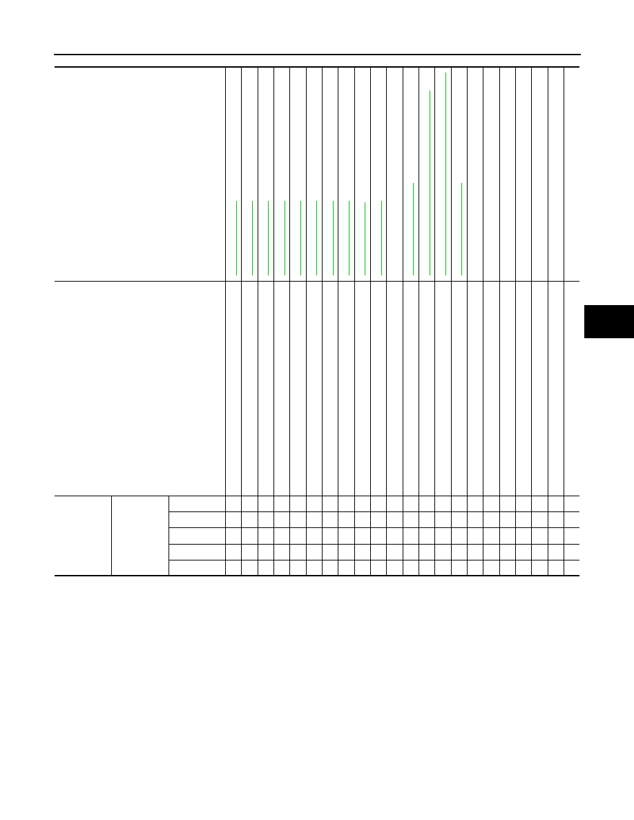
NOISE, VIBRATION AND HARSHNESS (NVH) TROUBLESHOOTING

ST-5

< SYMPTOM DIAGNOSIS >

C

D

E

F

H

I

J

K

L

M

A

B

ST

N

O

P

×

: Applicable

Reference

ST

-1

0,

 "

Inspe

c

ti

on

"

ST

-1

0,

 "

Inspe

c

ti

on

"

ST

-3

4,

 "

Inspe

c

ti

on

"

ST

-3

4,

 "

Inspe

c

ti

on

"

ST

-3

4,

 "

Inspe

c

ti

on

"

ST

-1

0,

 "

Inspe

c

ti

on

"

ST

-1

2,

 "

Inspe

c

ti

on

"

ST

-1

2,

 "

Inspe

c

ti

on

"

EM

-1

3

, "

Checking

"

ST

-1

2,

 "

Inspe

c

ti

on

"

ST

-2

4,

 "

Ex

pl

od

ed

 V

iew

"

ST

-2

0,

 "

WITH 

E

L

ECTRIC MOT

O

R : 

In

sp

ecti

on

"

ST

-1

9,

 "

WITH E

L

ECTRIC 

MOT

O

: Ex

pl

od

ed

 V

iew

"


ST

-2

4,

 "

Ex

pl

od

ed

 V

iew

"

NVH in DLN 

section.

NVH in DLN 

section.

NVH in F

AX, 

RAX, FSU, 

RSU section.

NVH in WT 

section.

NVH in WT 

section.

NVH in F

AX,

 RAX 

secti

on.

NVH in BR 

section.

Possible cause and SUSPECTED PARTS

Fl

ui

d l

e

v

e

l

Ai

r in

 hy

d

raul

ic

 s

y

s

tem

Ou

ter/i

n

n

e

s

o

ck

et ba

ll joi

n

t swin

gi

ng

 to

rqu

e

Ou

ter/i

n

n

e

so

cket ba

ll joi

n

t rot

a

tin

g

 torq

ue

Ou

ter/i

n

n

e

s

o

ck

et ba

ll joi

n

t en

p

la

y

S

tee

rin

g

 f

lui

d l

e

a

k

a

g

e

S

te

e

ri

ng

 whe

e

l pl

ay

S

te

e

ri

ng

 ge

ar ra

ck s

lid

in

g f

o

rc

e

Dri

ve b

el

lo

os

en

es

s

Im

p

rope

r s

tee

rin

g

 wh

ee

l

Im

p

rope

r i

n

s

tal

lat

io

n

 o

r lo

os

en

es

of 

til

t lo

ck

 l

e

v

e

r

M

ou

nti

ng

 lo

os

en

es

s

S

tee

rin

g

 c

o

lu

m

n

 d

e

fo

rm

ati

o

n

 or 

da

ma

ge

Im

p

rope

r i

n

s

tal

lat

io

n

 o

r lo

os

en

es

of 

ste

e

ri

ng

 c

o

lu

mn

S

tee

rin

g l

ink

a

ge 

lo

os

en

es

s

PROPELLER SHAFT

DIF

F

ERENTIA

L

AX

LE and SUSPE

N

S

ION

TI

RE

ROAD WHE

E

L

DRIVE

 SHAFT

BRAK

E

Symptom

Steering

Noise

× × × × × × × × ×

× ×

× × × × × × ×

Shake

×

×

×

× × × × ×

Vibration

×

× × ×

×

× ×

×

Shimmy

×

×

×

× × ×

×

Judder

×

×

× × ×

×

Revision: 2008 October

2009 Murano

ST-6

< PRECAUTION >

PRECAUTIONS

PRECAUTION

PRECAUTIONS

Precaution for Supplemental Restraint System (SRS) "AIR BAG" and "SEAT BELT 
PRE-TENSIONER"

INFOID:0000000003464623

The Supplemental Restraint System such as “AIR BAG” and “SEAT BELT PRE-TENSIONER”, used along
with a front seat belt, helps to reduce the risk or severity of injury to the driver and front passenger for certain
types of collision. This system includes seat belt switch inputs and dual stage front air bag modules. The SRS
system uses the seat belt switches to determine the front air bag deployment, and may only deploy one front
air bag, depending on the severity of a collision and whether the front occupants are belted or unbelted.
Information necessary to service the system safely is included in the “SRS AIRBAG” and “SEAT BELT” of this
Service Manual.

WARNING:

• To avoid rendering the SRS inoperative, which could increase the risk of personal injury or death in

the event of a collision which would result in air bag inflation, all maintenance must be performed by
an authorized NISSAN/INFINITI dealer.

• Improper maintenance, including incorrect removal and installation of the SRS, can lead to personal

injury caused by unintentional activation of the system. For removal of Spiral Cable and Air Bag
Module, see the “SRS AIRBAG”.

• Never use electrical test equipment on any circuit related to the SRS unless instructed to in this Ser-

vice Manual. SRS wiring harnesses can be identified by yellow and/or orange harnesses or harness
connectors.

PRECAUTIONS WHEN USING POWER TOOLS (AIR OR ELECTRIC) AND HAMMERS

When working near the Airbag Diagnosis Sensor Unit or other Airbag System sensors while ignition switch is
ON or engine is running, never use air or electric power tools or strike near the sensor(s) with a hammer.
Heavy vibration may activate the sensor(s), deploy the airbag(s), possibly cause serious injury.
When using air or electric power tools or hammers, always turn OFF ignition switch, disconnect the battery,
and wait 3 minutes or more before performing any service.

Precaution Necessary for Steering Wheel Rotation after Battery Disconnect

INFOID:0000000003305892

NOTE:
• Before removing and installing any control units, first turn the push-button ignition switch to the LOCK posi-

tion, then disconnect both battery cables.

• After finishing work, confirm that all control unit connectors are connected properly, then re-connect both

battery cables.

• Always use CONSULT-III to perform self-diagnosis as a part of each function inspection after finishing work.

If a DTC is detected, perform trouble diagnosis according to self-diagnosis results.

This vehicle is equipped with a push-button ignition switch and a steering lock unit.
If the battery is disconnected or discharged, the steering wheel will lock and cannot be turned.
If turning the steering wheel is required with the battery disconnected or discharged, follow the procedure
below before starting the repair operation.

OPERATION PROCEDURE

1.

Connect both battery cables.
NOTE:
Supply power using jumper cables if battery is discharged.

2.

Carry the Intelligent Key or insert it to the key slot and turn the push-button ignition switch to ACC position.
(At this time, the steering lock will be released.)

3.

Disconnect both battery cables. The steering lock will remain released with both battery cables discon-
nected and the steering wheel can be turned.

4.

Perform the necessary repair operation.

5.

When the repair work is completed, re-connect both battery cables. With the brake pedal released, turn
the push-button ignition switch from ACC position to ON position, then to LOCK position. (The steering
wheel will lock when the push-button ignition switch is turned to LOCK position.)

6.

Perform self-diagnosis check of all control units using CONSULT-III.

Revision: 2008 October

2009 Murano

PRECAUTIONS

ST-7

< PRECAUTION >

C

D

E

F

H

I

J

K

L

M

A

B

ST

N

O

P

Service Notice or Precautions for Steering System

INFOID:0000000003305893

• In case of removing steering gear assembly, make the final tightening with grounded and unloaded vehicle

condition, and then check wheel alignment.

• Observe the following precautions when disassembling.
- Before disassembly, thoroughly clean the outside of the unit.
- Disassembly should be done in a clean work area. It is important to prevent the internal parts from becoming

contaminated by dirt or other foreign matter.

- For easier and proper assembly, place disassembled parts in order on a parts rack.
- Use nylon cloth or paper towels to clean the parts; common shop rags can leave lint that might interfere with

their operation.

- Never reuse non-reusable parts.
- Before assembling, apply the specified grease to the directed parts.

Revision: 2008 October

2009 Murano

ST-8

< PREPARATION >

PREPARATION

PREPARATION

PREPARATION

Special Service Tools

INFOID:0000000003305894

The actual shapes of Kent-Moore tools may differ from those of special service tools illustrated here.

Tool number
(Kent-Moore No.)
Tool name

Description

ST27180001
(J-25726-A)
Steering wheel puller

Removing steering wheel

ST3127S000
(J-25765-A)
Preload gauge

Inspecting sliding torque, steering torque, and 
rotating torque for ball joint

KV48104400
(

)

Teflon ring correcting tool
a: 50 mm (1.97 in) dia.
b: 36 mm (1.42 in) dia.
c: 100 mm (3.94 in)

Installing rack Teflon ring

KV48103400
(

)

Preload adapter

Inspecting rotating torque

ST35300000
(

)

Drift
a: 45.1 mm (1.776 in) dia.
b: 59.0 mm (2.323 in) dia.

Installing oil pump oil seal

ZZA0819D

ZZA0806D

S-NT550

ZZA0824D

ZZA0881D

Revision: 2008 October

2009 Murano

PREPARATION

ST-9

< PREPARATION >

C

D

E

F

H

I

J

K

L

M

A

B

ST

N

O

P

Commercial Service Tool

INFOID:0000000003305895

KV48103500
(J-26357)
Oil pressure gauge

Measuring oil pump relief pressure

KV48102500
(J-33914)
Oil pressure gauge adapter

Measuring oil pump relief pressure

Tool number
(Kent-Moore No.)
Tool name

Description

S-NT547

S-NT542

Tool number
Tool name

Description

Power tool

Loosening bolts and nuts

PBIC0190E

Revision: 2008 October

2009 Murano

ST-10

< ON-VEHICLE MAINTENANCE >

POWER STEERING FLUID

ON-VEHICLE MAINTENANCE

POWER STEERING FLUID

Inspection

INFOID:0000000003305896

FLUID LEVEL

1.

Check fluid level with engine stopped.

2.

Ensure that fluid level is between MIN and MAX.

3.

Fluid levels at HOT and COLD are different. Do not confuse
them.

CAUTION:

• The fluid level should not exceed the MAX line. Excessive fluid causes fluid leakage from the

cap.

• Never reuse drained power steering fluid.

FLUID LEAKAGE

Check hydraulic connections for fluid leakage, cracks, damage,
looseness, or wear.

1.

Run the engine until the fluid temperature reaches 50 to 80

°

C

(122 to 176

°

F) in reservoir tank, and keep engine speed idle.

2.

Turn steering wheel several times from full left stop to full right
stop.

3.

Hold steering wheel at each lock position for five seconds and
carefully check for fluid leakage.

CAUTION:

Never hold the steering wheel in a locked position for more
than 10 seconds. (There is the possibility that power steer-
ing oil pump assembly may be damaged.)

4.

If fluid leakage at connections is noticed, then loosen flare nut and then retighten. Do not overtighten con-
nector as this can damage O-ring, washer and connector.

5.

If fluid leakage from oil pump is noticed, check oil pump.

6.

Check steering gear boots for accumulation of fluid leaked from steering gear.

AIR BLEEDING HYDRAULIC SYSTEM

If air bleeding is not complete, the following symptoms can be observed.
• Bubbles are created in reservoir tank.
• Clicking noise can be heard from oil pump.
• Excessive buzzing in the oil pump.

NOTE:
Fluid noise may occur in the steering gear or oil pump. This does not affect performance or durability of the
system.

1.

Turn steering wheel several times from full left stop to full right stop with engine off.

CAUTION:

Fill reservoir tank with a sufficient amount of fluid so that fluid level is not below the MIN line while
turning steering wheel.

HOT (A)

: Fluid temperature 50 – 80

°

C (122 – 176

°

F)

COLD (B)

: Fluid temperature 0 – 30

°

C (32 – 86

°

F)

Recommended fluid

: Refer to 

MA-15, "FOR 

NORTH AMERICA : Fluids 
and Lubricants"

.

Fluid capacity

: Refer to 

ST-44, "General 

Specifications"

.

ALGIA0002GB

SGIA0506E

Revision: 2008 October

2009 Murano

POWER STEERING FLUID

ST-11

< ON-VEHICLE MAINTENANCE >

C

D

E

F

H

I

J

K

L

M

A

B

ST

N

O

P

2.

Start the engine and hold steering wheel at each lock position for 3 second at idle to check for fluid leak-
age.

3.

Repeat step 2 above several times at approximately 3 second intervals.

CAUTION:

Never hold the steering wheel in a locked position for more than 10 seconds. (There is the possi-
bility that oil pump may be damaged.)

4.

Check fluid for bubbles and white contamination.

5.

Stop the engine if bubbles and white contamination do not drain out. Perform step 2 and 3 above after
waiting until bubbles and white contamination drain out.

6.

Stop the engine, and then check fluid level.

Revision: 2008 October

2009 Murano

ST-12

< ON-VEHICLE MAINTENANCE >

STEERING WHEEL

STEERING WHEEL

Inspection

INFOID:0000000003305897

STEERING WHEEL AXIAL END PLAY

1.

Check installation conditions of steering gear assembly, front suspension assembly, axle and steering col-
umn assembly.

2.

Check if movement exists when steering wheel is moved up and down, to the left and right and to the axial
direction.

3.

Check the following items when steering wheel axial end play is out of the standard.
• Check the steering column assembly mounting condition. Refer to 

ST-16, "WITHOUT ELECTRIC

MOTOR : Exploded View"

 (Without electric motor), 

ST-19, "WITH ELECTRIC MOTOR : Exploded View"

(with electric motor).

• Check steering gear assembly mounting condition for looseness. Refer to 

ST-24, "Exploded View"

.

STEERING WHEEL PLAY

1.

Turn steering wheel so that front wheels come to the straight-ahead position.

2.

Start the engine and lightly turn steering wheel to the left and right until front wheels start to move.

3.

Measure steering wheel movement on the outer circumference.

4.

Check the following items when steering wheel play is out of the standard.
• Check backlash for each joint of steering column assembly.
• Check installation condition of steering gear assembly.

NEUTRAL POSITION STEERING WHEEL

1.

Check that steering gear assembly, steering column assembly and steering wheel are installed in the cor-
rect position.

2.

Perform neutral position inspection after wheel alignment. Refer to 

FSU-9, "Inspection"

.

3.

Set the vehicle to the straight-ahead position and confirm steering wheel is in the neutral position.

4.

Loosen outer socket lock nut and turn inner socket to left and right equally to make fine adjustments if
steering wheel is not in the neutral position.

STEERING WHEEL TURNING FORCE

1.

Park the vehicle on a level and dry surface, set parking brake.

2.

Tires need to be inflated normal pressure. Refer to 

WT-111, "Tire Air Pressure"

.

3.

Start the engine.

4.

Bring power steering fluid up to adequate operating temperature.

Standard

Steering wheel axial end 
play

: Refer to 

ST-44, "Steering 

Wheel Axial End Play and 
Play"

.

Standard

Steering wheel play

: Refer to 

ST-44, "Steering 

Wheel Axial End Play and 
Play"

.

Fluid temperature

: 50 – 80

°

C (122 – 176

°

F)

Revision: 2008 October

2009 Murano

STEERING WHEEL

ST-13

< ON-VEHICLE MAINTENANCE >

C

D

E

F

H

I

J

K

L

M

A

B

ST

N

O

P

5.

Check steering wheel turning force when steering wheel has
been turned 540

°

 from neutral position.

NOTE:
Multiply the distance (L) from the hook of spring balance to the
center of steering wheel by the measurement value with a spring
balance.

6.

If steering wheel turning force is out of the specification, check
rack sliding force and relief hydraulic pressure of oil pump. Regarding relief hydraulic pressure of oil
pump, refer to 

ST-40, "Inspection"

.

RACK SLIDING FORCE

1.

Disconnect lower joint and steering knuckle from steering gear assembly. Refer to 

ST-22, "Exploded

View"

.

2.

Start and run the engine at idle to make sure steering fluid has reached normal operating temperature.

3.

While pulling outer socket slowly in 

±

11.5 mm (

±

0.453 in) range

from neutral position, make sure rack sliding force is within
specification.

4.

If rack sliding force is not within specification, overhaul steering
gear assembly.

FRONT WHEEL TURNING ANGLE

1.

Check front wheel turning angle after toe-in inspection. Refer to 

FSU-9, "Inspection"

.

2.

Place front wheels on turning radius gauges and rear wheels on
stands, so that vehicle can be level.

3.

Check the maximum inner and outer wheel turning angles for LH
and RH road wheels.

4.

With the engine at idle, turn steering wheel from full left stop to
full right stop and measure the turning angles.

Standard

Steering wheel turning 
force

: Refer to 

ST-44, "Steering 

Wheel Turning Force"

.

JSGIA0027ZZ

Fluid temperature

: 50 – 80

°

C (122 – 176

°

F)

Standard

Rack sliding force

: Refer to 

ST-45, "Rack 

Sliding Force"

.

SST090B

FAA0016D

Standard

Inner wheel (Angle: A)

: Refer to 

ST-44, "Steering 

Angle"

.

Outer wheel (Angle: B)

: Refer to 

ST-44, "Steering 

Angle"

.

SGIA0055E

Revision: 2008 October

2009 Murano

ST-14

< ON-VEHICLE MAINTENANCE >

STEERING WHEEL

5.

Check the following items when turning angle is out of the stan-
dard.

a.

Check the neutral position of the rack stroke (L).

b.

Disassemble steering gear assembly to check the cause that
rack stroke is outside of the standard.
• Steering angles are not adjustable. Check steering gear

assembly, steering column assembly and front suspension
components for wear or damage if any of the turning angles are different from the specified value.
Replace any of them, if any non-standard condition exists.

Standard

L

: Refer to 

ST-45, "Rack 

Stroke"

.

SGIA0629J

Revision: 2008 October

2009 Murano

STEERING WHEEL

ST-15

< ON-VEHICLE REPAIR >

C

D

E

F

H

I

J

K

L

M

A

B

ST

N

O

P

ON-VEHICLE REPAIR

STEERING WHEEL

Exploded View

INFOID:0000000003305898

Removal and Installation

INFOID:0000000003305899

REMOVAL

NOTE:
When reconnecting spiral cable, fix cable with a tape so that fixing case and rotating part keep aligned. This
will omit neutral position alignment procedure during spiral cable installation.
1.

Set the vehicle to the straight-ahead position.

2.

Remove driver air bag module. Refer to 

SR-5, "Exploded View"

.

3.

Remove steering wheel lock nut after steering is locked.

4.

Remove steering wheel with the steering wheel puller (A) [SST:
ST27180001 (J-25726-A)].

INSTALLATION

Note the following, and install in the reverse order of removal.

CAUTION:

Never twist spiral cable freely on excessively after it becomes tight (doing so may cause the cable to
tear off).
NOTE:
Check the spiral cable neutral position after replacing or rotating spiral cable. Refer to 

SR-8, "Exploded View"

1.

Steering wheel

Refer to 

GI-4, "Components"

 for symbols in the figure.

JSGIA0303GB

JSGIA0304ZZ

Revision: 2008 October

2009 Murano

ST-16

< ON-VEHICLE REPAIR >

STEERING COLUMN

STEERING COLUMN

WITHOUT ELECTRIC MOTOR

WITHOUT ELECTRIC MOTOR : Exploded View

INFOID:0000000003305900

WITHOUT ELECTRIC MOTOR : Removal and Installation

INFOID:0000000003305901

REMOVAL

1.

Set the vehicle to the straight-ahead position.

2.

Place the tilt to the highest level. Place the telescopic to the longest level.

3.

Remove driver air bag module. Refer to 

SR-5, "Exploded View"

.

4.

Remove steering wheel. Refer to 

ST-15, "Exploded View"

.

5.

Remove instrument driver lower panel. Refer to 

IP-11, "Exploded View"

.

6.

Remove steering column cover. Refer to 

IP-11, "Exploded View"

.

7.

Remove spiral cable. Refer to 

SR-5, "Exploded View"

.

8.

Remove cluster lid A. Refer to 

MWI-145, "Exploded View"

.

1.

Steering column assembly

2.

Bracket

3.

Bracket

4.

Slide plate

5.

Slide bracket

6.

Lower mount bracket

7.

Bracket

8.

Upper joint

9.

Spring

10. Tilt lever

11.

Clip

Refer to 

GI-4, "Components"

 for symbols in the figure.

JSGIA0610GB

Revision: 2008 October

2009 Murano

STEERING COLUMN

ST-17

< ON-VEHICLE REPAIR >

C

D

E

F

H

I

J

K

L

M

A

B

ST

N

O

P

9.

Remove knee protector (1).

10. Disconnect each switch harness connectors installed to steering

column assembly.

11. Remove the joint mounting bolt and nut (lower shaft side), and

separate the joint from lower shaft.

12. Remove steering column assembly.

CAUTION:

• Never give axial impact to steering column assembly dur-

ing removal.

• Never move steering gear assembly when removing steering column assembly.

INSTALLATION

Note the following, and install in the reverse order of removal.
• Install the slide plate (1) and steering column housing (2) so that

the mounting dimensions (L) is within the specified range as
described below.           

• Tighten the mounting bolts in the order shown in the figure when

installing the steering column assembly.

• Be careful of the following points when installing the steering col-

umn assembly.

CAUTION:

• Never give axial impact to steering column assembly during

installation.

• Never move steering gear assembly.
• Never reuse the joint mounting nut (lower shaft side).

• Adjust neutral position of steering angle sensor. Refer to 

BRC-9,

"ADJUSTMENT OF STEERING ANGLE SENSOR NEUTRAL
POSITION : Special Repair Requirement"

.

WITHOUT ELECTRIC MOTOR : Inspection

INFOID:0000000003305902

INSPECTION AFTER REMOVAL

• Check each part of steering column assembly for damage or other malfunctions. Replace if necessary.
• Measure steering column assembly rotating torque using a preload gauge [SST: ST3127S000 (J-25765-A)].

Replace steering column assembly if outside the standard.

: Bolt

JSGIA0306ZZ

Standard

L

: 2.0 mm (0.079 in) or less

JSGIA0315ZZ

JSGIA0310ZZ

Standard

Rotating torque

: Refer to 

ST-44, "Steering 

Column Operating 
Range"

.

Revision: 2008 October

2009 Murano

ST-18

< ON-VEHICLE REPAIR >

STEERING COLUMN

• Measure the length (L) as shown, if vehicle has been involved in a

minor collision. Replace steering column assembly if out side the
standard.

• Install the bracket (1) and steering column housing (2) so that the

clearance (A) is within the specified range as described below.
Replace steering column assembly if out side the standard.

INSPECTION AFTER INSTALLATION

• Check each part of steering column assembly for damage or other malfunctions. Replace if necessary.
• Check the steering wheel play, neutral position steering wheel, steering wheel turning force, and front wheel

turning angle. Refer to 

ST-12, "Inspection"

.

• Check tilt and telescopic mechanism operating range tilt operating

range (L), telescopic operating range (T) as shown in the figure.

WITH ELECTRIC MOTOR

Standard

L

: Refer to 

ST-44, "Steering 

Column Length"

.

JSGIA0562ZZ

Standard

A

: Refer to 

ST-44, "Steering 

Column Mounting Dimen-
sions"

.

JSGIA0389ZZ

Standard

T

:  Refer  to 

ST-44, "Steering 

Column Operating 
Range"

.

L

:  Refer  to 

ST-44, "Steering 

Column Operating 
Range"

.

JSGIA0307ZZ

Revision: 2008 October

2009 Murano

STEERING COLUMN

ST-19

< ON-VEHICLE REPAIR >

C

D

E

F

H

I

J

K

L

M

A

B

ST

N

O

P

WITH ELECTRIC MOTOR : Exploded View

INFOID:0000000003305903

WITH ELECTRIC MOTOR : Removal and Installation

INFOID:0000000003349525

REMOVAL

1.

Set the vehicle to the straight-ahead position.

2.

Place the tilt to the highest level. Place the telescopic to the longest level.

3.

Remove driver air bag module. Refer to 

SR-5, "Exploded View"

.

4.

Remove steering wheel. Refer to 

ST-15, "Exploded View"

.

5.

Remove instrument driver lower panel. Refer to 

IP-11, "Exploded View"

.

6.

Remove steering column cover. Refer to 

IP-11, "Exploded View"

.

7.

Remove spiral cable. Refer to 

SR-8, "Exploded View"

.

8.

Remove cluster lid A. Refer to 

MWI-145, "Exploded View"

.

1.

Bracket

2.

Steering column assembly

3.

Bracket

4.

Clip

5.

Tilt motor

6.

Bracket

7.

Bracket

8.

Bracket

9.

Slide bracket

10. Lower mount bracket

11.

Upper joint

12. Bracket

13. Telescopic motor

14. Bracket

15. Bracket

Refer to 

GI-4, "Components"

 for symbols in the figure.

JSGIA0529GB

Revision: 2008 October

2009 Murano

ST-20

< ON-VEHICLE REPAIR >

STEERING COLUMN

9.

Remove knee protector (1).

10. Disconnect each switch harness connectors installed to steering

column assembly.

11. Remove the joint mounting bolt and nut (lower shaft side), and

separate the joint from lower shaft.

12. Remove steering column assembly.

CAUTION:

• Never give axial impact to steering column assembly dur-

ing removal.

• Never move steering gear assembly when removing steering column assembly.

INSTALLATION

Note the following, and install in the reverse order of removal.
• Install the slide plate (1) and steering column housing (2) so that

the mounting dimensions (L) is within the specified range as
described below.           

• Tighten the mounting bolts in the order shown in the figure when

installing the steering column assembly.

• Be careful of the following points when installing the steering col-

umn assembly.

CAUTION:

• Never give axial impact to steering column assembly during

installation.

• Never move steering gear assembly.
• Never reuse the joint mounting nut (lower shaft side).

• Adjust neutral position of steering angle sensor. Refer to 

BRC-9,

"ADJUSTMENT OF STEERING ANGLE SENSOR NEUTRAL
POSITION : Special Repair Requirement"

.

WITH ELECTRIC MOTOR : Inspection

INFOID:0000000003305905

INSPECTION AFTER REMOVAL

• Check each part of steering column assembly for damage or other malfunctions. Replace if necessary.
• Measure steering column assembly rotating torque using a preload gauge [SST: ST3127S000 (J-25765-A)].

Replace steering column assembly if outside the standard.

: Bolt

JSGIA0306ZZ

Standard

L

: 2.0 mm (0.079 in) or less

JSGIA0315ZZ

JSGIA0310ZZ

Standard

Rotating torque

: Refer to 

ST-44, "Steering 

Column Operating 
Range"

.

Revision: 2008 October

2009 Murano


Content      ..     368      369      370      371     ..