Nissan Murano Z51 (2008 year). Manual - part 360
SRC-176
< FUNCTION DIAGNOSIS >
[FOR MEXICO]
SRS AIR BAG SYSTEM
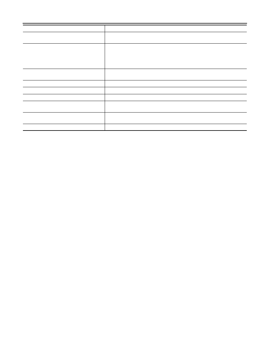
Component
Function
Air bag diagnosis sensor unit
Detects a collision and supplies power supply for deployment to air bag module and
pre-tensioner seat belt.
Air bag module
• Driver
• Passenger
• Side
• Curtain
Receives signal from air bag diagnosis sensor unit and deploys air bag.
Seat belt pre-tensioner
Receives signal from air bag diagnosis sensor unit and deploys seat belt pre-tension-
er.
Seat belt buckle switch
Controls deployment timing based on seat belt fastened or unfastened condition.
Crash zone sensor
Transmits signal to air bag diagnosis sensor unit when a frontal collision occurs.
Satellite sensor (LH/RH)
Transmits signal to air bag diagnosis sensor unit when a side collision occurs.
Combination meter (air bag warning lamp)
Indicates air bag malfunctioning and deployment by blinking and illuminating air bag
warning lamp.
Passenger air bag OFF indicator
Indicates whether or not passenger air bag is in the activation mode based on the
judgement of Occupant Classification System.
Combination switch (spiral cable)
Supplies power supply to driver air bag module on steering wheel.
Revision: 2008 October
2009 Murano