Nissan Murano Z51 (2008 year). Manual - part 347
FRONT PASSENGER AIR BAG MODULE
SR-11
< ON-VEHICLE REPAIR >
[FOR USA AND CANADA]
C
D
E
F
G
I
J
K
L
M
A
B
SR
N
O
P
FRONT PASSENGER AIR BAG MODULE
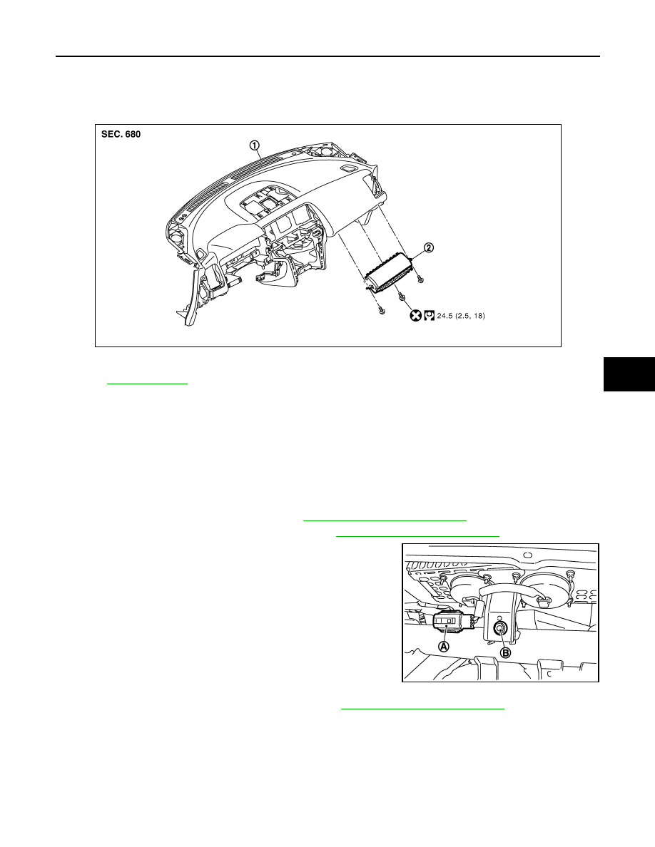
Exploded View
INFOID:0000000003367289
Removal and Installation
INFOID:0000000003367290
WARNING:
• Before servicing, turn ignition switch OFF, disconnect battery negative terminal and wait at least 3
minutes.
• Always work from the side of air bag module. Never work in front of it.
• Never use the air tools or electric tools for servicing.
REMOVAL
1.
Remove the glove box lid assembly. Refer to
IP-12, "Removal and Installation"
2.
Remove the Instrument lower assist panel. Refer to
IP-12, "Removal and Installation"
.
3.
Disconnect the front passenger air bag harness connector (A).
4.
Remove the front passenger air bag module fixing bolt (B).
NOTE:
The figure shows the installed front passenger air bag module.
(Under view of the module installed without glove box cover.)
5.
Remove the instrument panel assembly (1). Refer to
IP-12, "Removal and Installation"
.
1.
Instrument panel assembly
2.
Front passenger air bag module
Refer to
JMHIA0509GB
JMHIA0510ZZ
Revision: 2008 October
2009 Murano