Nissan Murano Z51 (2008 year). Manual - part 334
NISSAN VEHICLE IMMOBILIZER SYSTEM-NATS
SEC-247
< FUNCTION DIAGNOSIS >
[WITHOUT INTELLIGENT KEY SYSTEM]
C
D
E
F
G
H
I
J
L
M
A
B
SEC
N
O
P
ENGINE START FUNCTION : Component Description
INFOID:0000000003465854
10. Horn (low) E342, E343
11.
Control device (detection switch) M57
12. Stop lamp switch
TYPE A: E115
TYPE B: E116
13. Remote keyless entry receiver
A.
Behind the combination meter
B.
Engine room (LH)
C.
View with the center console as-
sembly removed
D.
Behind the instrument lower panel LH
E.
Behind the instrument lower panel RH
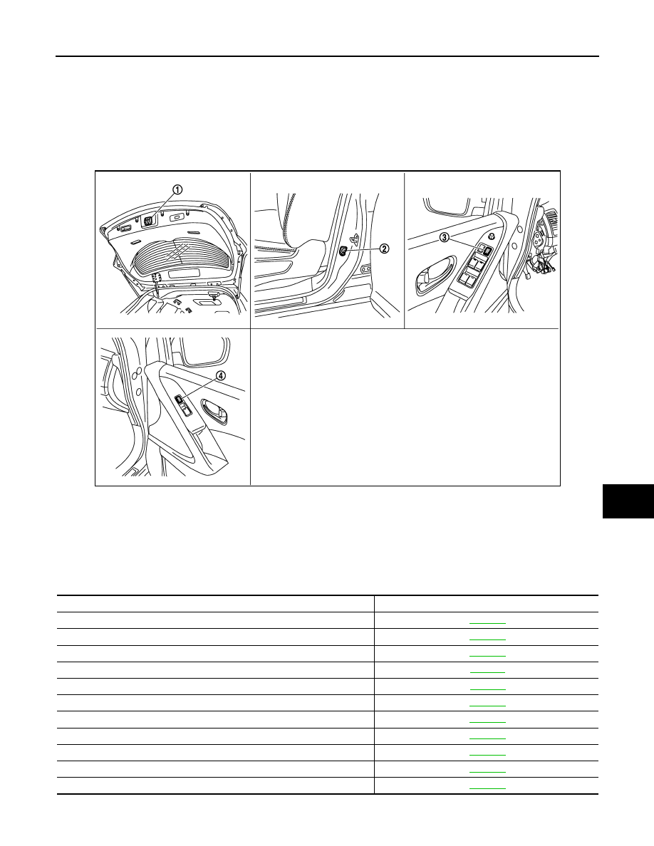
1.
Back door lock assembly (back door
switch) D180
2.
Front door switch (driver side) B34
3.
Power window main switch (door
lock and unlock switch) D5, D6
4.
Front power window switch (passen-
ger side) D45
JMKIA1913ZZ
Component Reference
BCM
Steering lock unit
Push-button ignition switch
Door switch
key slot
Control device (detention switch)
Stop lamp switch
Park/neutral position switch
Steering lock relay
Starter relay
Starter control relay
Revision: 2008 October
2009 Murano