Nissan Murano Z51 (2008 year). Manual - part 316
SE-94
< SYMPTOM DIAGNOSIS >
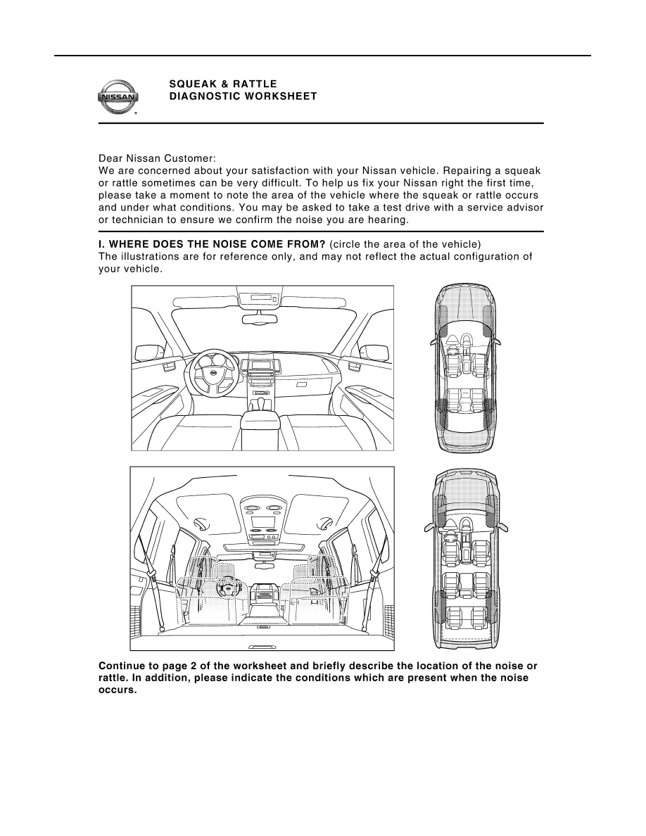
SQUEAK AND RATTLE TROUBLE DIAGNOSES
Diagnostic Worksheet
INFOID:0000000003690556
PIIB8740E
Revision: 2008 October
2009 Murano
|
|
|
SE-94 < SYMPTOM DIAGNOSIS > SQUEAK AND RATTLE TROUBLE DIAGNOSES Diagnostic Worksheet INFOID:0000000003690556 PIIB8740E Revision: 2008 October 2009 Murano |