Nissan Murano Z51 (2008 year). Manual - part 284
 

  Index      Manuals     Nissan Murano Z51 (2008 year) - Service and Repair Manual


Search            copyright infringement  


Content      ..     282      283      284      285     ..


Nissan Murano Z51 (2008 year). Manual - part 284


PCS

BCM (BODY CONTROL MODULE)

PCS-115

< ECU DIAGNOSIS >

[POWER DISTRIBUTION SYSTEM]

C

D

E

F

G

H

I

J

K

L

B

A

O

P

N

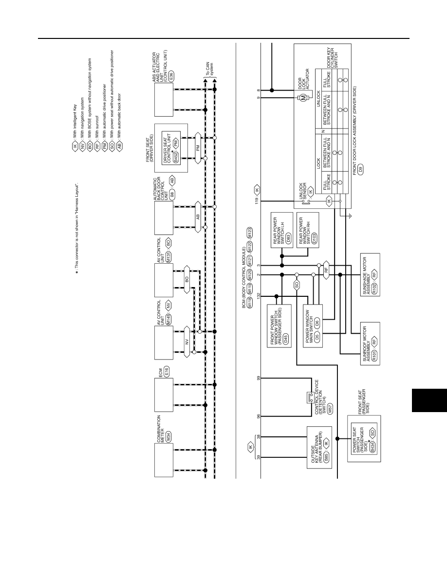
JCMWM3161GB

Revision: 2008 October

2009 Murano

PCS-116

< ECU DIAGNOSIS >

[POWER DISTRIBUTION SYSTEM]

BCM (BODY CONTROL MODULE)

JCMWM3162GB

Revision: 2008 October

2009 Murano

PCS

BCM (BODY CONTROL MODULE)

PCS-117

< ECU DIAGNOSIS >

[POWER DISTRIBUTION SYSTEM]

C

D

E

F

G

H

I

J

K

L

B

A

O

P

N

JCMWM3163GB

Revision: 2008 October

2009 Murano

PCS-118

< ECU DIAGNOSIS >

[POWER DISTRIBUTION SYSTEM]

BCM (BODY CONTROL MODULE)

JCMWM3164GB

Revision: 2008 October

2009 Murano

PCS

BCM (BODY CONTROL MODULE)

PCS-119

< ECU DIAGNOSIS >

[POWER DISTRIBUTION SYSTEM]

C

D

E

F

G

H

I

J

K

L

B

A

O

P

N

Fail-safe

INFOID:0000000004757395

FAIL-SAFE CONTROL BY DTC

BCM performs fail-safe control when any DTC are detected.

JCMWM3165GB

Revision: 2008 October

2009 Murano

PCS-120

< ECU DIAGNOSIS >

[POWER DISTRIBUTION SYSTEM]

BCM (BODY CONTROL MODULE)

Display contents of CONSULT

Fail-safe

Cancellation

B2013: ID DISCORD BCM-S/L

Inhibit engine cranking

Erase DTC

B2014: CHAIN OF S/L-BCM

Inhibit engine cranking

Erase DTC

B2190: NATS ANTENNA AMP

Inhibit engine cranking

Erase DTC

B2191: DIFFERENCE OF KEY

Inhibit engine cranking

Erase DTC

B2192: ID DISCORD BCM-ECM

Inhibit engine cranking

Erase DTC

B2193: CHAIN OF BCM-ECM

Inhibit engine cranking

Erase DTC

B2195: ANTI SCANNING

Inhibit engine cranking

Ignition switch ON 

 OFF

B2557: VEHICLE SPEED

Inhibit steering lock

When normal vehicle speed signals are received from ABS actua-
tor and electric unit (control unit) for 500 ms

B2560: STARTER CONT RELAY

Inhibit engine cranking

500 ms after the following CAN signal communication status be-
comes consistent
• Starter control relay signal
• Starter relay status signal

B2601: SHIFT POSITION

Inhibit steering lock

500 ms after the following signal reception status becomes consis-
tent
• Selector lever P position switch signal
• P range signal (CAN)

B2602: SHIFT POSITION

Inhibit steering lock

5 seconds after the following BCM recognition conditions are ful-
filled
• Ignition switch is in the ON position
• Selector lever P position switch signal: Except P position (battery 

voltage)

• Vehicle speed: 4 km/h (2.5 MPH) or more

B2603: SHIFT POSI STATUS

Inhibit steering lock

500 ms after the following BCM recognition conditions are fulfilled
• Ignition switch is in the ON position
• Selector lever P position switch signal: Except P position (battery 

voltage)

• Selector lever P/N position signal: Except P and N positions (0 V)

B2604: PNP SW

Inhibit steering lock

500 ms after any of the following BCM recognition conditions are 
fulfilled
• Status  1
- Ignition switch is in the ON position
- Selector lever P/N position signal: P and N position (battery volt-

age)

- P range signal or N range signal (CAN): ON
• Status  2
- Ignition switch is in the ON position
- Selector lever P/N position signal: Except P and N positions (0 V)
- P range signal and N range signal (CAN): OFF

B2605: PNP SW

Inhibit steering lock

500 ms after any of the following BCM recognition conditions are 
fulfilled
• Ignition switch is in the ON position
- Power position: IGN
- Selector lever P/N position signal: Except P and N positions (0 V)
- Interlock/PNP switch signal (CAN): OFF
• Status  2
- Ignition switch is in the ON position
- Selector lever P/N position signal: P or N position (battery volt-

age)

- PNP switch signal (CAN): ON

B2606: S/L RELAY

Inhibit engine cranking

500 ms after the following CAN signal communication status be-
comes consistent
• Steering lock relay signal (Request signal)
• Steering lock relay signal (Condition signal)

Revision: 2008 October

2009 Murano

PCS

BCM (BODY CONTROL MODULE)

PCS-121

< ECU DIAGNOSIS >

[POWER DISTRIBUTION SYSTEM]

C

D

E

F

G

H

I

J

K

L

B

A

O

P

N

HIGH FLASHER OPERATION

BCM detects the turn signal lamp circuit status by the current value.
BCM increases the turn signal lamp blinking speed if the bulb or harness open is detected with the turn signal
lamp operating.
NOTE:
The blinking speed is normal while activating the hazard warning lamp.

FAIL-SAFE CONTROL BY RAIN SENSOR MALFUNCTION

• BCM judges the rain sensor serial link error by the rain sensor serial link condition and detects the rain sen-

sor malfunction by rain sensor malfunction signal.

• When BCM detects the rain sensor serial link error or the rain sensor malfunction while front wiper AUTO

operation, BCM operates a fail-safe control.

NOTE:
If rain sensor malfunction is detected when ignition switch is turned OFF 

 ON and front wiper switch is INT/

AUTO position, BCM operates a fail-safe control.

REAR WIPER MOTOR PROTECTION

BCM detects the rear wiper stopping position according to the rear wiper stop position signal.
When the rear wiper stop position signal does not change for more than 5 seconds while driving the rear
wiper, BCM stops power supply to protect the rear wiper motor.

Condition of cancellation

1.

More than 1 minute is passed after the rear wiper stop.

B2607: S/L RELAY

Inhibit engine cranking

500 ms after the following CAN signal communication status be-
comes consistent
• Steering lock relay signal (Request signal)
• Steering lock relay signal (Condition signal)

B2608: STARTER RELAY

Inhibit engine cranking

500 ms after the following signal communication status becomes 
consistent
• Starter motor relay control signal
• Starter relay status signal (CAN)

B2609: S/L STATUS

• Inhibit engine cranking
• Inhibit steering lock

When the following steering lock conditions agree
• BCM steering lock control status
• Steering lock condition No. 1 signal status
• Steering lock condition No. 2 signal status

B260A: IGNITION RELAY

Inhibit engine cranking

500 ms after the following conditions are fulfilled
• IGN relay (IPDM E/R) control signal: OFF (Battery voltage)
• Ignition ON signal (CAN to IPDM E/R): OFF (Request signal)
• Ignition ON signal (CAN from IPDM E/R): OFF (Condition signal)

B260F: ENG STATE SIG LOST

Maintains the power supply 
position attained at the time 
of DTC detection

When any of the following conditions are fulfilled
• Power position changes to ACC
• Receives engine status signal (CAN)

B2612: S/L STATUS

• Inhibit engine cranking
• Inhibit steering lock

When any of the following conditions are fulfilled
• Steering lock unit status signal (CAN) is received normally
• The BCM steering lock control status matches the steering lock 

status recognized by the steering lock unit status signal (CAN 
from IPDM E/R)

B2617: STARTER RELAY CIRC

Inhibit engine cranking

1 second after the starter motor relay control inside BCM becomes 
normal

B2618: BCM

Inhibit engine cranking

1 second after the ignition relay (IPDM E/R) control inside BCM be-
comes normal

B2619: BCM

Inhibit engine cranking

1 second after the steering lock unit power supply output control in-
side BCM becomes normal

B261E: VEHICLE TYPE

Inhibit engine cranking

BCM initialization

B26E9: S/L STATUS

• Inhibit engine cranking
• Inhibit steering lock

When BCM transmits the LOCK request signal to steering lock unit, 
and receives LOCK response signal from steering lock unit, the fol-
lowing conditions are fulfilled
• Steering condition No. 1 signal: LOCK (0V)
• Steering condition No. 2 signal: LOCK (Battery voltage)

Display contents of CONSULT

Fail-safe

Cancellation

Revision: 2008 October

2009 Murano

PCS-122

< ECU DIAGNOSIS >

[POWER DISTRIBUTION SYSTEM]

BCM (BODY CONTROL MODULE)

2.

Turn rear wiper switch OFF.

3.

Operate the rear wiper switch or rear washer switch.

DTC Inspection Priority Chart

INFOID:0000000004757396

If some DTCs are displayed at the same time, perform inspections one by one based on the following priority
chart.

Priority

DTC

1

B2562: LOW VOLTAGE

2

• U1000: CAN COMM CIRCUIT
• U1010: CONTROL UNIT (CAN)

3

• B2190: NATS ANTENNA AMP
• B2191: DIFFERENCE OF KEY
• B2192: ID DISCORD BCM-ECM
• B2193: CHAIN OF BCM-ECM
• B2195: ANTI SCANNING

4

• B2013: ID DISCORD BCM-S/L
• B2014: CHAIN OF S/L-BCM
• B2553: IGNITION RELAY
• B2555: STOP LAMP 
• B2556: PUSH-BTN IGN SW
• B2557: VEHICLE SPEED
• B2560: STARTER CONT RELAY
• B2601: SHIFT POSITION
• B2602: SHIFT POSITION
• B2603: SHIFT POSI STATUS
• B2604: PNP SW
• B2605: PNP SW
• B2606: S/L RELAY
• B2607: S/L RELAY
• B2608: STARTER RELAY
• B2609: S/L STATUS
• B260A: IGNITION RELAY
• B260B: STEERING LOCK UNIT
• B260C: STEERING LOCK UNIT
• B260D: STEERING LOCK UNIT
• B260F: ENG STATE SIG LOST
• B2612: S/L STATUS
• B2614: ACC RELAY CIRC
• B2615: BLOWER RELAY CIRC
• B2616: IGN RELAY CIRC
• B2617: STARTER RELAY CIRC
• B2618: BCM
• B2619: BCM
• B261A: PUSH-BTN IGN SW
• B261E: VEHICLE TYPE
• B26E9: S/L STATUS
• B26EA: KEY REGISTRATION
• C1729: VHCL SPEED SIG ERR
• U0415: VEHICLE SPEED SIG

Revision: 2008 October

2009 Murano

PCS

BCM (BODY CONTROL MODULE)

PCS-123

< ECU DIAGNOSIS >

[POWER DISTRIBUTION SYSTEM]

C

D

E

F

G

H

I

J

K

L

B

A

O

P

N

DTC Index

INFOID:0000000004757397

NOTE:
The details of time display are as follows.
• CRNT: A malfunction is detected now.
• PAST: A malfunction was detected in the past.
IGN counter is displayed on Freeze Frame Data. For details of Freeze Frame Data, refer to 

BCS-17, "COM-

MON ITEM : CONSULT-III Function (BCM - COMMON ITEM)"

.

5

• C1704: LOW PRESSURE FL
• C1705: LOW PRESSURE FR
• C1706: LOW PRESSURE RR
• C1707: LOW PRESSURE RL
• C1708: [NO DATA] FL
• C1709: [NO DATA] FR
• C1710: [NO DATA] RR
• C1711: [NO DATA] RL
• C1712: [CHECKSUM ERR] FL
• C1713: [CHECKSUM ERR] FR
• C1714: [CHECKSUM ERR] RR
• C1715: [CHECKSUM ERR] RL
• C1716: [PRESSDATA ERR] FL
• C1717: [PRESSDATA ERR] FR
• C1718: [PRESSDATA ERR] RR
• C1719: [PRESSDATA ERR] RL
• C1720: [CODE ERR] FL
• C1721: [CODE ERR] FR
• C1722: [CODE ERR] RR
• C1723: [CODE ERR] RL
• C1724: [BATT VOLT LOW] FL
• C1725: [BATT VOLT LOW] FR
• C1726: [BATT VOLT LOW] RR
• C1727: [BATT VOLT LOW] RL
• C1734: CONTROL UNIT

6

• B2621: INSIDE ANTENNA 
• B2622: INSIDE ANTENNA 
• B2623: INSIDE ANTENNA 

Priority

DTC

CONSULT display

Fail-safe

Freeze Frame 

Data

•Vehicle Speed

•Odo/Trip Meter

•Vehicle Condi-

tion

Intelligent Key 

warning lamp ON

Tire pressure 

monitor warning 

lamp ON

Reference 

page

No DTC is detected.
further testing
may be required.

U1000: CAN COMM CIRCUIT

BCS-40

U1010: CONTROL UNIT (CAN)

BCS-41

U0415: VEHICLE SPEED SIG

BCS-42

B2013: ID DISCORD BCM-S/L

×

×

SEC-55

B2014: CHAIN OF S/L-BCM

×

×

SEC-56

B2190: NATS ANTENNA AMP

×

SEC-47

B2191: DIFFERENCE OF KEY

×

SEC-50

B2192: ID DISCORD BCM-ECM

×

SEC-51

B2193: CHAIN OF BCM-ECM

×

SEC-53

B2195: ANTI SCANNING

×

SEC-54

B2553: IGNITION RELAY

×

PCS-49

Revision: 2008 October

2009 Murano

PCS-124

< ECU DIAGNOSIS >

[POWER DISTRIBUTION SYSTEM]

BCM (BODY CONTROL MODULE)

B2555: STOP LAMP

×

SEC-59

B2556: PUSH-BTN IGN SW

×

×

SEC-61

B2557: VEHICLE SPEED

×

×

×

SEC-63

B2560: STARTER CONT RELAY

×

×

×

SEC-64

B2562: LOW VOLTAGE

×

BCS-43

B2601: SHIFT POSITION

×

×

×

SEC-65

B2602: SHIFT POSITION

×

×

×

SEC-68

B2603: SHIFT POSI STATUS

×

×

×

SEC-70

B2604: PNP SW

×

×

×

SEC-73

B2605: PNP SW

×

×

×

SEC-75

B2606: S/L RELAY

×

×

×

SEC-77

B2607: S/L RELAY

×

×

×

SEC-78

B2608: STARTER RELAY

×

×

×

SEC-80

B2609: S/L STATUS

×

×

×

SEC-82

B260A: IGNITION RELAY

×

×

×

PCS-51

B260B: STEERING LOCK UNIT

×

×

SEC-86

B260C: STEERING LOCK UNIT

×

×

SEC-87

B260D: STEERING LOCK UNIT

×

×

SEC-88

B260F: ENG STATE SIG LOST

×

×

×

SEC-89

B2612: S/L STATUS

×

×

×

SEC-92

B2614: ACC RELAY CIRC

×

×

PCS-53

B2615: BLOWER RELAY CIRC

×

×

PCS-56

B2616: IGN RELAY CIRC

×

×

PCS-59

B2617: STARTER RELAY CIRC

×

×

×

SEC-96

B2618: BCM

×

×

×

PCS-62

B2619: BCM

×

×

×

SEC-98

B261A: PUSH-BTN IGN SW

×

×

SEC-99

B261E: VEHICLE TYPE

×

×

×

 (Turn ON for 15 

seconds)

SEC-102

B2621: INSIDE ANTENNA

×

DLK-95

B2622: INSIDE ANTENNA

×

DLK-97

B2623: INSIDE ANTENNA

×

DLK-99

B26E9: S/L STATUS

×

×

×

 (Turn ON for 15 

seconds)

SEC-90

B26EA: KEY REGISTRATION

×

×

 (Turn ON for 15 

seconds)

SEC-91

C1704: LOW PRESSURE FL

×

WT-16

C1705: LOW PRESSURE FR

×

C1706: LOW PRESSURE RR

×

C1707: LOW PRESSURE RL

×

CONSULT display

Fail-safe

Freeze Frame 

Data

•Vehicle Speed

•Odo/Trip Meter

•Vehicle Condi-

tion

Intelligent Key 

warning lamp ON

Tire pressure 

monitor warning 

lamp ON

Reference 

page

Revision: 2008 October

2009 Murano

PCS

BCM (BODY CONTROL MODULE)

PCS-125

< ECU DIAGNOSIS >

[POWER DISTRIBUTION SYSTEM]

C

D

E

F

G

H

I

J

K

L

B

A

O

P

N

C1708: [NO DATA] FL

×

WT-18

C1709: [NO DATA] FR

×

C1710: [NO DATA] RR

×

C1711: [NO DATA] RL

×

C1712: [CHECKSUM ERR] FL

×

WT-21

C1713: [CHECKSUM ERR] FR

×

C1714: [CHECKSUM ERR] RR

×

C1715: [CHECKSUM ERR] RL

×

C1716: [PRESSDATA ERR] FL

×

WT-24

C1717: [PRESSDATA ERR] FR

×

C1718: [PRESSDATA ERR] RR

×

C1719: [PRESSDATA ERR] RL

×

C1720: [CODE ERR] FL

×

WT-26

C1721: [CODE ERR] FR

×

C1722: [CODE ERR] RR

×

C1723: [CODE ERR] RL

×

C1724: [BATT VOLT LOW] FL

×

WT-29

C1725: [BATT VOLT LOW] FR

×

C1726: [BATT VOLT LOW] RR

×

C1727: [BATT VOLT LOW] RL

×

C1729: VHCL SPEED SIG ERR

×

WT-32

C1734: CONTROL UNIT

×

WT-33

CONSULT display

Fail-safe

Freeze Frame 

Data

•Vehicle Speed

•Odo/Trip Meter

•Vehicle Condi-

tion

Intelligent Key 

warning lamp ON

Tire pressure 

monitor warning 

lamp ON

Reference 

page

Revision: 2008 October

2009 Murano

PCS-126

< PRECAUTION >

[POWER DISTRIBUTION SYSTEM]

PRECAUTIONS

PRECAUTION

PRECAUTIONS

Precaution for Supplemental Restraint System (SRS) "AIR BAG" and "SEAT BELT 
PRE-TENSIONER"

INFOID:0000000004757477

The Supplemental Restraint System such as “AIR BAG” and “SEAT BELT PRE-TENSIONER”, used along
with a front seat belt, helps to reduce the risk or severity of injury to the driver and front passenger for certain
types of collision. This system includes seat belt switch inputs and dual stage front air bag modules. The SRS
system uses the seat belt switches to determine the front air bag deployment, and may only deploy one front
air bag, depending on the severity of a collision and whether the front occupants are belted or unbelted.
Information necessary to service the system safely is included in the “SRS AIRBAG” and “SEAT BELT” of this
Service Manual.

WARNING:

• To avoid rendering the SRS inoperative, which could increase the risk of personal injury or death in

the event of a collision which would result in air bag inflation, all maintenance must be performed by
an authorized NISSAN/INFINITI dealer.

• Improper maintenance, including incorrect removal and installation of the SRS, can lead to personal

injury caused by unintentional activation of the system. For removal of Spiral Cable and Air Bag
Module, see the “SRS AIRBAG”.

• Never use electrical test equipment on any circuit related to the SRS unless instructed to in this Ser-

vice Manual. SRS wiring harnesses can be identified by yellow and/or orange harnesses or harness
connectors.

PRECAUTIONS WHEN USING POWER TOOLS (AIR OR ELECTRIC) AND HAMMERS

When working near the Airbag Diagnosis Sensor Unit or other Airbag System sensors while ignition switch is
ON or engine is running, never use air or electric power tools or strike near the sensor(s) with a hammer.
Heavy vibration may activate the sensor(s), deploy the airbag(s), possibly cause serious injury.
When using air or electric power tools or hammers, always turn OFF ignition switch, disconnect the battery,
and wait 3 minutes or more before performing any service.

Precaution Necessary for Steering Wheel Rotation after Battery Disconnect

INFOID:0000000004757478

NOTE:
• Before removing and installing any control units, first turn the push-button ignition switch to the LOCK posi-

tion, then disconnect both battery cables.

• After finishing work, confirm that all control unit connectors are connected properly, then re-connect both

battery cables.

• Always use CONSULT-III to perform self-diagnosis as a part of each function inspection after finishing work.

If a DTC is detected, perform trouble diagnosis according to self-diagnosis results.

This vehicle is equipped with a push-button ignition switch and a steering lock unit.
If the battery is disconnected or discharged, the steering wheel will lock and cannot be turned.
If turning the steering wheel is required with the battery disconnected or discharged, follow the procedure
below before starting the repair operation.

OPERATION PROCEDURE

1.

Connect both battery cables.
NOTE:
Supply power using jumper cables if battery is discharged.

2.

Turn the push-button ignition switch to ACC position.
(At this time, the steering lock will be released.)

3.

Disconnect both battery cables. The steering lock will remain released with both battery cables discon-
nected and the steering wheel can be turned.

4.

Perform the necessary repair operation.

5.

When the repair work is completed, re-connect both battery cables. With the brake pedal released, turn
the push-button ignition switch from ACC position to ON position, then to LOCK position. (The steering
wheel will lock when the push-button ignition switch is turned to LOCK position.)

6.

Perform self-diagnosis check of all control units using CONSULT-III.

Revision: 2008 October

2009 Murano

PCS

PUSH-BUTTON IGNITION SWITCH DOES NOT OPERATE

PCS-127

< SYMPTOM DIAGNOSIS >

[POWER DISTRIBUTION SYSTEM]

C

D

E

F

G

H

I

J

K

L

B

A

O

P

N

SYMPTOM DIAGNOSIS

PUSH-BUTTON IGNITION SWITCH DOES NOT OPERATE

Description

INFOID:0000000004757291

Check that vehicle is under the condition shown in “Conditions of vehicle” before starting diagnosis, and check
each symptom.
NOTE:
The engine start function, door lock function, power distribution system, and NATS-IVIS/NVIS in the Intelligent
Key system are closely related to each other regarding control. The vehicle security function can operate only
when the door lock and power distribution system are operating normally.

Conditions of Vehicle (Operating Conditions)

With Intelligent Key system

• “ENGINE START BY I-KEY” in “WORK SUPPORT” is ON when setting on CONSULT-III.
• Intelligent Key is not inserted in key slot.
• One or more of Intelligent Keys with registered Intelligent Key ID is in the vehicle.

Without Intelligent Key system

Registered keyfob is into the key slot.

Diagnosis Procedure

INFOID:0000000004757292

1.

INSPECTION START

Check the vehicle type.

Which is the type?

With Intelligent Key system>>GO TO 2.
Without Intelligent Key system>>GO TO 4.

2.

PERFORM WORK SUPPORT

Perform “INSIDE ANT DIAGNOSIS” on Work Support of “INTELLIGENT KEY”.
Refer to 

DLK-61, "INTELLIGENT KEY : CONSULT-III Function (BCM - INTELLIGENT KEY)"

.

>> GO TO 3.

3.

PERFORM SELF-DIAGNOSTIC RESULT

Perform Self-Diagnostic Result of “BCM”.
Is DTC detected?

YES

>> Refer to 

DLK-95, "DTC Logic"

 (instrument center), 

DLK-97, "DTC Logic"

 (console) or 

DLK-99,

"DTC Logic"

 (trunk room).

NO

>> GO TO 4.

4.

CHECK PUSH-BUTTON IGNITION SWITCH

Check push-button ignition switch.
Refer to 

PCS-66, "Component Function Check"

.

Is the operation normal?

YES

>> GO TO 5.

NO

>> Repair or replace malfunctioning parts.

5.

CONFIRM THE OPERATION

Confirm the operation again.
Is the inspection normal?

YES

>> Check intermittent incident. Refer to 

GI-40, "Intermittent Incident"

.

NO

>> GO TO 1.

Revision: 2008 October

2009 Murano

PCS-128

< SYMPTOM DIAGNOSIS >

[POWER DISTRIBUTION SYSTEM]

PUSH-BUTTON IGNITION SWITCH POSITION INDICATOR DOES NOT ILLUMI-

NATE

PUSH-BUTTON IGNITION SWITCH POSITION INDICATOR DOES NOT IL-
LUMINATE

Description

INFOID:0000000003465788

• Before performing the diagnosis in the following table, check “Work Flow”. Refer to 

PCS-35, "Work Flow"

.

• Check that vehicle is under the condition shown in “Conditions of vehicle” before starting diagnosis, and

check each symptom.

Conditions of Vehicle (Operating Conditions)

• “ENGINE START BY I-KEY” in “WORK SUPPORT” is ON when setting on CONSULT-III.
• One or more of Intelligent Keys with registered Intelligent Key ID is in the vehicle.
• Registered keyfob is into the key slot. (Without Intelligent key system)

Diagnosis Procedure

INFOID:0000000003375919

1.

CHECK PUSH-BUTTON IGNITION SWITCH INDICATOR

Check push-button ignition switch indicator.
Refer to 

PCS-68, "Component Function Check"

.

Is the inspection result normal?

YES

>> GO TO 2.

NO

>> Repair or replace the malfunctioning parts.

2.

CONFIRM THE OPERATION

Confirm the operation again.

Is the result normal?

YES

>> Check intermittent incident. Refer to 

GI-40, "Intermittent Incident"

.

NO

>> GO TO 1.

Revision: 2008 October

2009 Murano

PCS

BCM (BODY CONTROL MODULE)

PCS-129

< ON-VEHICLE REPAIR >

[POWER DISTRIBUTION SYSTEM]

C

D

E

F

G

H

I

J

K

L

B

A

O

P

N

ON-VEHICLE REPAIR

BCM (BODY CONTROL MODULE)

Exploded View

INFOID:0000000004757479

CAUTION:

Before replacing BCM, perform “READ CONFIGURATION” to save or print current vehicle specifica-
tion. Refer to 

BCS-3, "ADDITIONAL SERVICE WHEN REPLACING CONTROL UNIT (BCM) : Descrip-

tion"

.

Removal and Installation

INFOID:0000000004757480

CAUTION:

Before replacing BCM, perform “READ CONFIGURATION” to save or print current vehicle specifica-
tion. Refer to 

BCS-3, "ADDITIONAL SERVICE WHEN REPLACING CONTROL UNIT (BCM) : Descrip-

tion"

.

REMOVAL

1.

Remove combination meter. Refer to 

MWI-145, "Exploded View"

.

2.

Remove screws.

3.

Remove BCM and disconnect the connector.

INSTALLATION

Install in the reverse order of removal.

CAUTION:

• Be sure to perform “WRITE CONFIGURATION” when replacing BCM.
• Be sure to perform the system initialization (NATS) when replacing BCM. Refer to 

BCS-3, "ADDI-

TIONAL SERVICE WHEN REPLACING CONTROL UNIT (BCM) : Special Repair Requirement"

.

1.

BCM

JPMIA0895ZZ

Revision: 2008 October

2009 Murano

PCS-130

< ON-VEHICLE REPAIR >

[POWER DISTRIBUTION SYSTEM]

PUSH BUTTON IGNITION SWITCH

PUSH BUTTON IGNITION SWITCH

Exploded View

INFOID:0000000003466131

Removal and Installation

INFOID:0000000003466132

REMOVAL

1.

Remove the instrument stay cover LH. Refer to 

IP-12, "Removal and Installation"

.

2.

Remove the push-button ignition switch (1) from instrument stay
cover LH, after removing pawl (A). Press push-button ignition
switch (1) back to disengage from instrument stay cover LH (2).

INSTALLATION

Install in the reverse order of removal.

1.

Push-button ignition switch

JMKIA1812ZZ

JMKIA1813ZZ

Revision: 2008 October

2009 Murano


Content      ..     282      283      284      285     ..