Nissan Murano Z51 (2008 year). Manual - part 274
MWI
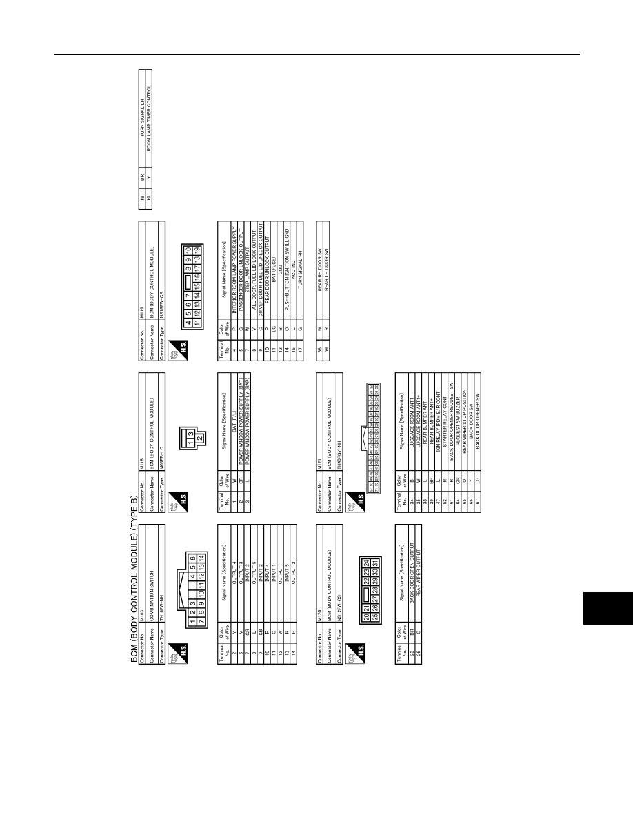
BCM (BODY CONTROL MODULE)
MWI-113
< ECU DIAGNOSIS >
C
D
E
F
G
H
I
J
K
L
M
B
A
O
P
JCMWM3164GB
Revision: 2008 October
2009 Murano
|
|
|
MWI BCM (BODY CONTROL MODULE) MWI-113 < ECU DIAGNOSIS > C D E F G H I J K L M B A O P JCMWM3164GB Revision: 2008 October 2009 Murano |