Nissan Murano Z51 (2008 year). Manual - part 243
VANITY MIRROR LAMP
INL-117
< ON-VEHICLE REPAIR >
C
D
E
F
G
H
I
J
K
M
A
B
INL
N
O
P
VANITY MIRROR LAMP
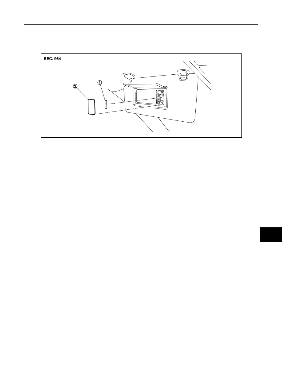
Exploded View
INFOID:0000000003295139
Replacement
INFOID:0000000003295140
CAUTION:
• Disconnect the battery negative terminal or remove the fuse.
• Never touch the glass of bulb directly by hand. Keep grease and other oily matters away from it.
• Never touch bulb by hand while it is lit or right after being turned off.
• Never leave bulb out of lamp reflector for a long time because dust, moisture smoke, etc. may affect
the performance of lamp. When replacing bulb, be sure to replace it with new one.
VANITY MIRROR LAMP BULB
1.
Insert any appropriate tool into the gap between the lens. Remove the lens.
2.
Remove the bulb.
1.
Bulb
2.
Lens
JPLIA0988ZZ
Revision: 2008 October
2009 Murano