Nissan Murano Z51 (2008 year). Manual - part 242
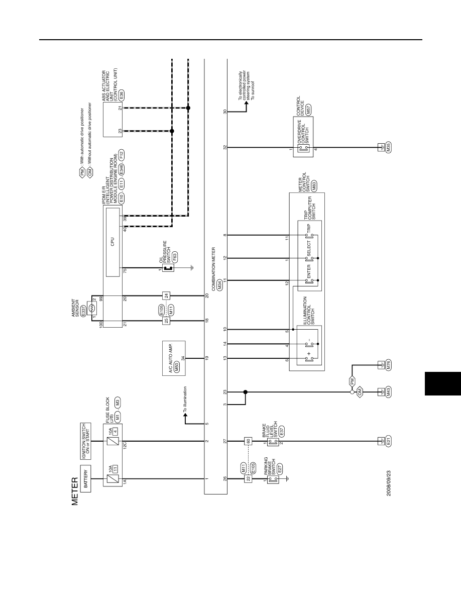
COMBINATION METER
INL-101
< ECU DIAGNOSIS >
C
D
E
F
G
H
I
J
K
M
A
B
INL
N
O
P
• Type B: From VIN: JN8AZ18U*9W100001, JN8AZ18W*9W200001 (EXCEPT FOR MEXICO),
JN8AZ18U*9W710001, JN8AZ18W*9W810001 (FOR MEXICO)
JCNWM1816GB
Revision: 2008 October
2009 Murano