Nissan Murano Z51 (2008 year). Manual - part 235


  Index      Manuals     Nissan Murano Z51 (2008 year) - Service and Repair Manual


Search            copyright infringement  


Content      ..     233      234      235      236     ..


Nissan Murano Z51 (2008 year). Manual - part 235


PRECAUTIONS

HAC-235

< PRECAUTION >

[WITH 7 INCH DISPLAY]

C

D

E

F

G

H

J

K

L

M

A

B

HAC

N

O

P

• Keep refrigerant away from open flames. Poisonous gas is produced if refrigerant burns.
• Refrigerant displaces oxygen, therefore be certain to work in well ventilated areas to prevent suffo-

cation.

• Never pressure test or leakage test HFC-134a (R-134a) service equipment and/or vehicle air condi-

tioning systems with compressed air during repair. Some mixtures of air and HFC-134a (R-134a)
have been shown to be combustible at elevated pressures. These mixtures, if ignited, may cause
injury or property damage. Additional health and safety information may be obtained from refriger-
ant manufacturers.

Refrigerant Connection

INFOID:0000000003469383

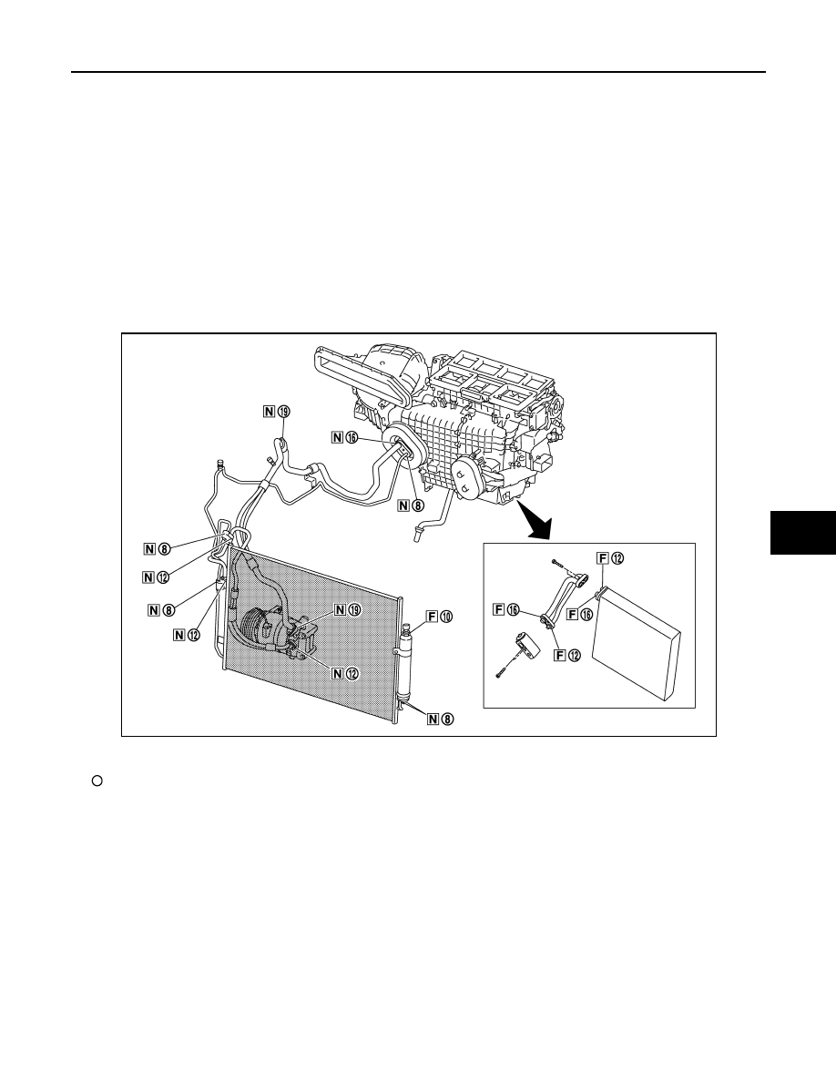
A new type refrigerant connection has been introduced to all refrigerant lines except the following location.
• Expansion valve to evaporator
• Refrigerant pressure sensor to liquid tank

O-RING AND REFRIGERANT CONNECTION

CAUTION:

The new and former refrigerant connections use different O-ring configurations. Never confuse O-
rings since they are not interchangeable. Refrigerant may leak at the connection if a wrong O-ring is
installed.

O-Ring Part Numbers and Specifications

F.

Former type refrigerant connection

N.

New type refrigerant connection

:

O-ring size

JPIIA0453ZZ

Revision: 2008 October

2009 Murano

HAC-236

< PRECAUTION >

[WITH 7 INCH DISPLAY]

PRECAUTIONS

WARNING:

Check that all refrigerant is discharged into the recycling equipment and the pressure in the system is
less than atmospheric pressure. Then gradually loosen the discharge side hose fitting and remove it.

CAUTION:

Observe the following when replacing or cleaning refrigerant cycle components.
• Store it in the same way at it is when mounted on the car when the compressor is removed. Failure

to do so will cause lubricant to enter the low-pressure chamber.

• Always use a torque wrench and a back-up wrench when connecting tubes.
• Immediately plug all openings to prevent entry of dust and moisture after disconnecting tubes.
• Connect the pipes at the final stage of the operation when installing an air conditioner in the vehicle.

Never remove the seal caps of pipes and other components until just before required for connection.

• Allow components stored in cool areas to warm to working area temperature before removing seal

caps. This prevents condensation from forming inside A/C components.

• Thoroughly remove moisture from the refrigeration system before charging the refrigerant.
• Replace always used O-rings.
• Apply lubricant to circle of the O-rings shown in illustration when connecting tube. Be careful not to

apply lubricant to threaded portion.

• O-ring must be closely attached to the groove portion of tube.
• Be careful not to damage O-ring and tube when replacing the O-ring.
• Connect tube until a click can be heard. Then tighten the nut or bolt by hand. Check that the O-ring is

installed to tube correctly.

Connection type

Piping connection point

Part number

QTY

O-ring size

New

Low-pressure flexible hose to low-pressure pipe

92474 N8210

1

φ

19

High-pressure pipe to condenser pipe assembly (Outlet)

92471 N8210

1

φ

8

Condenser pipe assembly (Inlet) to high-pressure flexible 
hose (One-touch joint)

92472 N8210

1

φ

12

Condenser assembly to condenser pipe as-
sembly

Inlet

92472 N8210

1

φ

12

Outlet

92471 N8210

1

φ

8

Low-pressure pipe to expansion valve

92473 N8210

1

φ

16

High-pressure pipe to expansion valve

92471 N8210

1

φ

8

Compressor to low-pressure flexible hose

92474 N8210

1

φ

19

Compressor to high-pressure flexible hose

92472 N8210

1

φ

12

Liquid tank to condenser assembly

Inlet

92471 N8210

1

φ

8

Outlet

1

Former

Refrigerant pressure sensor to liquid tank

J2476 89956

1

φ

10

Expansion valve to evaporator pipe assembly

Inlet

92475 71L00

1

φ

12

Outlet

92475 72L00

1

φ

16

Evaporator to evaporator pipe assembly

Inlet

92475 71L00

1

φ

12

Outlet

92475 72L00

1

φ

16

Name

: NISSAN A/C System Oil Type S

Revision: 2008 October

2009 Murano

PRECAUTIONS

HAC-237

< PRECAUTION >

[WITH 7 INCH DISPLAY]

C

D

E

F

G

H

J

K

L

M

A

B

HAC

N

O

P

• Perform leakage test and make sure that there is no leakage from connections after connecting line.

Disconnect the line and replace the O-ring when the refrigerant leaking point is found. Then tighten
the connections of seal seat to the specified torque.

Service Equipment

INFOID:0000000003469384

RECOVERY/RECYCLING EQUIPMENT

Be certain to follow the manufacturer instructions for machine operation and machine maintenance. Never
introduce any refrigerant other than that specified into the machine.

ELECTRICAL LEAK DETECTOR

Be certain to follow the manufacturer instructions for tester operation and tester maintenance.

VACUUM PUMP

The lubricant contained inside the vacuum pump is not compatible
with the specified lubricant for HFC-134a (R-134a) A/C systems.
The vent side of the vacuum pump is exposed to atmospheric pres-
sure. So the vacuum pump lubricant may migrate out of the pump
into the service hose. This is possible when the pump is switched
OFF after evacuation (vacuuming) and hose is connected to it.
To prevent this migration, use a manual valve placed near the hose-
to-pump connection, as per the following.
• Vacuum pumps usually have a manual isolator valve as part of the

pump. Close this valve to isolate the service hose from the pump.

• Use a hose equipped with a manual shut-off valve near the pump

end for pumps without an isolator. Close the valve to isolate the
hose from the pump.

• Disconnect the hose from the pump if the hose has an automatic

shut-off valve. As long as the hose is connected, the valve is open
and lubricating oil may migrate.

Some one-way valves open when vacuum is applied and close
under no vacuum condition. Such valves may restrict the ability of
the pump to create a deep vacuum and are not recommended.

MANIFOLD GAUGE SET

RHA861F

RHA270DA

Revision: 2008 October

2009 Murano

HAC-238

< PRECAUTION >

[WITH 7 INCH DISPLAY]

PRECAUTIONS

Be certain that the gauge face indicates HFC-134a or R-134a. Be
sure the gauge set has 1/2

-16 ACME threaded connections for ser-

vice hoses. Confirm the set has been used only with refrigerant
HFC-134a (R-134a) and specified lubricants.

SERVICE HOSES

Be certain that the service hoses display the markings described
(colored hose with a black stripe). All hoses must equip positive
shut-off devices (either manual or automatic) near the end of the
hoses opposite to the manifold gauge.

SERVICE COUPLERS

Never attempt to connect HFC-134a (R-134a) service couplers to a
CFC-12 (R-12) A/C system. The HFC-134a (R-134a) couplers do
not properly connect to the CFC-12 (R-12) system. However, if an
improper connection is attempted, discharge and contamination may
occur.

REFRIGERANT WEIGHT SCALE

Verify that no refrigerant other than HFC-134a (R-134a) and speci-
fied lubricants have been used with the scale. The hose fitting must
be 1/2

-16 ACME if the scale controls refrigerant flow electronically.

CHARGING CYLINDER

Use of a charging cylinder is not recommended. Refrigerant may be vented into the air from the top valve of
the cylinder when filling the cylinder with refrigerant. Also, the accuracy of the cylinder is generally less than
that of an electronic scale or of quality recycle/recharge equipment.

SHA533D

RHA272D

Shut-off valve rotation

A/C service valve

Clockwise

Open

Counterclockwise

Close

RHA273D

RHA274D

Revision: 2008 October

2009 Murano

COMPRESSOR

HAC-239

< PRECAUTION >

[WITH 7 INCH DISPLAY]

C

D

E

F

G

H

J

K

L

M

A

B

HAC

N

O

P

COMPRESSOR

General Precautions

INFOID:0000000003469385

CAUTION:

• Plug all openings to prevent moisture and foreign matter from entering.
• Store it in the same way at it is when mounted on the car when the compressor is removed.
• Follow “Maintenance of Lubricant Quantity in Compressor” exactly when replacing or repairing the

compressor. Refer to 

HA-25, "Maintenance of Lubricant Quantity"

.

• Keep friction surfaces between clutch and pulley clean. Wipe it off by using a clean waste cloth

moistened with thinner if the surface is contaminated with lubricant.

• Turn the compressor shaft by hand more than five turns in both directions after compressor service

operation. This equally distributes lubricant inside the compressor. Let the engine idle and operate
the compressor for one hour after the compressor is installed.

• Apply voltage to the new compressor and check for normal operation after replacing the compressor

magnet clutch.

Revision: 2008 October

2009 Murano

HAC-240

< PRECAUTION >

[WITH 7 INCH DISPLAY]

FLUORESCENT LEAK DETECTOR

FLUORESCENT LEAK DETECTOR

General Precautions

INFOID:0000000003469386

CAUTION:

• The A/C system contains a fluorescent leak detection dye used for locating refrigerant leakages. An

ultraviolet (UV) lamp is required to illuminate the dye when inspecting for leakages.

• Always wear fluorescence enhancing UV safety goggles to protect eyes and enhance the visibility of

the fluorescent dye.

• The fluorescent dye leak detector is not a replacement for an electrical leak detector (SST: J-41995).

The fluorescent dye leak detector should be used in conjunction with an electrical leak detector
(SST: J-41995) to pin-point refrigerant leakages.

• Read and follow all manufacture operating instructions and precautions prior to performing the work

for the purpose of safety and customer satisfaction.

• A compressor shaft seal should not necessarily be repaired because of dye seepage. The compres-

sor shaft seal should only be repaired after confirming the leakage with an electrical leak detector
(SST: J-41995).

• Always remove any remaining dye from the leakage area after repairs are completed to avoid a mis-

diagnosis during future service.

• Never allow dye to come into contact with painted body panels or interior components. Clean imme-

diately with the approved dye cleaner if dye is spilled. Fluorescent dye left on a surface for an
extended period of time cannot be removed.

• Never spray the fluorescent dye cleaning agent on hot surfaces (engine exhaust manifold, etc.).
• Never use more than one refrigerant dye bottle (1/4 ounce /7.4 cc) per A/C system.
• Leak detection dyes for HFC-134a (R-134a) and CFC-12 (R-12) A/C systems are different. Never use

HFC-134a (R-134a) leak detection dye in CFC-12 (R-12) A/C system, or CFC-12 (R-12) leak detection
dye in HFC-134a (R-134a) A/C system, or A/C system damage may result.

• The fluorescent properties of the dye remains for three or more years unless a compressor malfunc-

tion occurs.

IDENTIFICATION

NOTE:
Vehicles with factory installed fluorescent dye have a green label.
Vehicles without factory installed fluorescent dye have a blue label.

IDENTIFICATION LABEL FOR VEHICLE

Vehicles with factory installed fluorescent dye have an identification label on the front side of hood.

Revision: 2008 October

2009 Murano

HRN-2

< COMPONENT DIAGNOSIS >

HORN

COMPONENT DIAGNOSIS

HORN

Wiring Diagram - HORN -

INFOID:0000000003307699

JCLWM2824GB

Revision: 2008 October

2009 Murano

HORN

HRN-3

< COMPONENT DIAGNOSIS >

C

D

E

F

G

H

I

J

K

M

A

B

HRN

N

O

P

JCLWM2825GB

Revision: 2008 October

2009 Murano

HRN-4

< COMPONENT DIAGNOSIS >

HORN

JCLWM2826GB

Revision: 2008 October

2009 Murano

PRECAUTIONS

HRN-5

< PRECAUTION >

C

D

E

F

G

H

I

J

K

M

A

B

HRN

N

O

P

PRECAUTION

PRECAUTIONS

Precaution for Supplemental Restraint System (SRS) "AIR BAG" and "SEAT BELT 
PRE-TENSIONER"

INFOID:0000000004788566

The Supplemental Restraint System such as “AIR BAG” and “SEAT BELT PRE-TENSIONER”, used along
with a front seat belt, helps to reduce the risk or severity of injury to the driver and front passenger for certain
types of collision. This system includes seat belt switch inputs and dual stage front air bag modules. The SRS
system uses the seat belt switches to determine the front air bag deployment, and may only deploy one front
air bag, depending on the severity of a collision and whether the front occupants are belted or unbelted.
Information necessary to service the system safely is included in the “SRS AIRBAG” and “SEAT BELT” of this
Service Manual.

WARNING:

• To avoid rendering the SRS inoperative, which could increase the risk of personal injury or death in

the event of a collision which would result in air bag inflation, all maintenance must be performed by
an authorized NISSAN/INFINITI dealer.

• Improper maintenance, including incorrect removal and installation of the SRS, can lead to personal

injury caused by unintentional activation of the system. For removal of Spiral Cable and Air Bag
Module, see the “SRS AIRBAG”.

• Never use electrical test equipment on any circuit related to the SRS unless instructed to in this Ser-

vice Manual. SRS wiring harnesses can be identified by yellow and/or orange harnesses or harness
connectors.

PRECAUTIONS WHEN USING POWER TOOLS (AIR OR ELECTRIC) AND HAMMERS

When working near the Airbag Diagnosis Sensor Unit or other Airbag System sensors while ignition switch is
ON or engine is running, never use air or electric power tools or strike near the sensor(s) with a hammer.
Heavy vibration may activate the sensor(s), deploy the airbag(s), possibly cause serious injury.
When using air or electric power tools or hammers, always turn OFF ignition switch, disconnect the battery,
and wait 3 minutes or more before performing any service.

Revision: 2008 October

2009 Murano

HRN-6

< ON-VEHICLE REPAIR >

HORN

ON-VEHICLE REPAIR

HORN

Exploded View

INFOID:0000000003307701

Removal and Installation

INFOID:0000000003307702

REMOVAL

1.

Remove the front grille. Refer to 

EXT-18, "Exploded View"

.

2.

Disconnect the horn (LOW, HIGH) connector.

3.

Remove the horn mounting nut, and remove the horn (LOW, HIGH) from the vehicle.

INSTALLATION

Install in the reverse order of removal.

1.

Horn (HIGH)

2.

Horn (LOW)

JPLIA1492ZZ

Revision: 2008 October

2009 Murano

INL-1

DRIVER CONTROLS

C

D

E

F

G

H

I

J

K

M

SECTION 

INL

A

B

INL

N

O

P

CONTENTS

INTERIOR LIGHTING SYSTEM

BASIC INSPECTION  ....................................

3

DIAGNOSIS AND REPAIR WORKFLOW  ..........

3

Work Flow  .................................................................

3

FUNCTION DIAGNOSIS ...............................

5

INTERIOR ROOM LAMP CONTROL SYSTEM 

.....

5

System Diagram ........................................................

5

System Description  ...................................................

5

Component Parts Location ........................................

7

Component Description ............................................

7

INTERIOR ROOM LAMP BATTERY SAVER 
SYSTEM ..............................................................

8

System Diagram ........................................................

8

System Description  ...................................................

8

Component Parts Location ........................................

9

Component Description ..........................................

10

ILLUMINATION CONTROL SYSTEM ................

11

System Diagram ......................................................

11

System Description  .................................................

11

Component Parts Location ......................................

12

Component Description ...........................................

12

DIAGNOSIS SYSTEM (BCM)  ............................

13

COMMON ITEM  .........................................................

13

COMMON ITEM : CONSULT-III Function (BCM - 
COMMON ITEM) .....................................................

13

INT LAMP  ..................................................................

14

INT LAMP : CONSULT-III Function (BCM - INT 
LAMP) .....................................................................

15

BATTERY SAVER  .....................................................

16

BATTERY SAVER : CONSULT-III Function (BCM 
- BATTERY SAVER)  ...............................................

16

COMPONENT DIAGNOSIS  .........................

18

POWER SUPPLY AND GROUND CIRCUIT  ....

18

BCM ...........................................................................

18

BCM : Diagnosis Procedure  ....................................

18

INTERIOR ROOM LAMP POWER SUPPLY 
CIRCUIT ............................................................

19

Description ...............................................................

19

Component Function Check  ....................................

19

Diagnosis Procedure  ...............................................

19

INTERIOR ROOM LAMP CONTROL CIRCUIT 

...

21

Description ...............................................................

21

Component Function Check  ....................................

21

Diagnosis Procedure  ...............................................

21

STEP LAMP CIRCUIT .......................................

23

Description ...............................................................

23

Component Function Check  ....................................

23

Diagnosis Procedure  ...............................................

23

PUSH-BUTTON IGNITION SWITCH ILLUMI-
NATION CIRCUIT  .............................................

25

Description ...............................................................

25

Component Function Check  ....................................

25

Diagnosis Procedure  ...............................................

25

INTERIOR ROOM LAMP CONTROL SYSTEM 

...

27

Wiring Diagram - INTERIOR ROOM LAMP -  ..........

27

ILLUMINATION .................................................

36

Wiring Diagram - ILLUMINATION -  .........................

36

ECU DIAGNOSIS .........................................

50

BCM (BODY CONTROL MODULE)  .................

50

Reference Value ......................................................

50

Wiring Diagram - BCM -  ..........................................

74

Fail-safe ...................................................................

88

DTC Inspection Priority Chart ...............................

91

Revision: 2008 October

2009 Murano

INL-2

DTC Index ..............................................................

92

COMBINATION METER  ....................................

95

Reference Value  .....................................................

95

Wiring Diagram - METER -  ....................................

100

Fail-Safe ................................................................

110

DTC Index  .............................................................

111

SYMPTOM DIAGNOSIS  ............................

112

INTERIOR LIGHTING SYSTEM SYMPTOMS .

112

Symptom Table  .....................................................

112

PRECAUTION ............................................

113

PRECAUTIONS  ...............................................

113

FOR USA AND CANADA  ........................................

113

FOR USA AND CANADA : Precaution for Supple-
mental Restraint System (SRS) "AIR BAG" and 
"SEAT BELT PRE-TENSIONER" ..........................

113

FOR MEXICO  ...........................................................

113

FOR MEXICO : Precaution for Supplemental Re-
straint System (SRS) "AIR BAG" and "SEAT BELT 
PRE-TENSIONER" ................................................

113

ON-VEHICLE REPAIR ...............................

115

MAP LAMP  ......................................................

115

Exploded View  .......................................................

115

Removal and Installation  .......................................

115

Replacement .........................................................

115

MOOD LAMP  ...................................................

116

MAP LAMP ...............................................................

116

MAP LAMP : Replacement  ....................................

116

FRONT DOOR GRIP ................................................

116

FRONT DOOR GRIP : Replacement .....................

116

ROOF CENTER  .......................................................

116

ROOF CENTER : Replacement ............................

116

VANITY MIRROR LAMP  ..................................

117

Exploded View  ......................................................

117

Replacement .........................................................

117

CONSOLE POCKET LAMP  .............................

118

Exploded View  ......................................................

118

Replacement .........................................................

118

ASHTRAY ILLUMINATION  ..............................

119

Exploded View  ......................................................

119

Replacement .........................................................

119

GLOVE BOX LAMP ..........................................

120

Exploded View  ......................................................

120

Replacement .........................................................

120

STEP LAMP ......................................................

121

Exploded View  ......................................................

121

Removal and Installation .......................................

121

Replacement .........................................................

121

PERSONAL LAMP  ...........................................

122

Exploded View  ......................................................

122

Removal and Installation .......................................

122

Replacement .........................................................

123

LUGGAGE ROOM LAMP .................................

124

Exploded View  ......................................................

124

Removal and Installation .......................................

124

Replacement .........................................................

124

SERVICE DATA AND SPECIFICATIONS 
(SDS) .........................................................

125

SERVICE DATA AND SPECIFICATIONS 
(SDS) ................................................................

125

Bulb Specifications ................................................

125

Revision: 2008 October

2009 Murano

DIAGNOSIS AND REPAIR WORKFLOW

INL-3

< BASIC INSPECTION >

C

D

E

F

G

H

I

J

K

M

A

B

INL

N

O

P

BASIC INSPECTION

DIAGNOSIS AND REPAIR WORKFLOW

Work Flow

INFOID:0000000003295090

OVERALL SEQUENCE

DETAILED FLOW

1.

INTERVIEW FOR MALFUNCTION

Interview the symptom to the customer.

JPLIA0313GB

Revision: 2008 October

2009 Murano

INL-4

< BASIC INSPECTION >

DIAGNOSIS AND REPAIR WORKFLOW

>> GO TO 2.

2.

SYMPTOM CHECK

Check the symptom from the customer's information.

>> GO TO 3.

3.

BASIC INSPECTION

Check the operation of each part. Check that any symptom occurs other than the interviewed symptom.

>> GO TO 4.

4.

SELF-DIAGNOSIS WITH CONSULT-III

Perform the self-diagnosis with CONSULT-III. Check that any DTC is detected.
Is any DTC detected?

YES

>> GO TO 5.

NO

>> GO TO 6.

5.

TROUBLE DIAGNOSIS BY DTC

Perform the trouble diagnosis for the detected DTC. Specify the malfunctioning part.

>> GO TO 9.

6.

FAIL-SAFE ACTIVATION CHECK

Check that the symptom is applied to the fail-safe activation.
Does the fail-safe activate?

YES

>> GO TO 7.

NO

>> GO TO 8.

7.

SYSTEM DIAGNOSIS

Perform the system diagnosis for the system that the fail-safe activates. Specify the malfunctioning part.

>> GO TO 9.

8.

SYMPTOM DIAGNOSIS

Perform the symptom diagnosis. Specify the malfunctioning part.

>> GO TO 9.

9.

MALFUNCTION PART REPAIR

Repair or replace the malfunctioning part.

>> GO TO 10.

10.

REPAIR CHECK (SELF-DIAGNOSIS WITH CONSULT-III)

Perform the self-diagnosis with CONSULT-III. Check that any DTC is not detected. Erase DTC if DTC is
detected before the repair. Check that DTC is not detected again.

Is any DTC detected?

YES

>> GO TO 5.

NO

>> GO TO 11.

11.

REPAIR CHECK (OPERATION CHECK)

Check the operation of each part.
Does it operate normally?

YES

>> INSPECTION END

NO

>> GO TO 3.

Revision: 2008 October

2009 Murano


Content      ..     233      234      235      236     ..