Nissan Murano Z51 (2008 year). Manual - part 213


  Index      Manuals     Nissan Murano Z51 (2008 year) - Service and Repair Manual


Search            copyright infringement  


Content      ..     211      212      213      214     ..


Nissan Murano Z51 (2008 year). Manual - part 213


GI-28

< PRECAUTION >

PRECAUTIONS

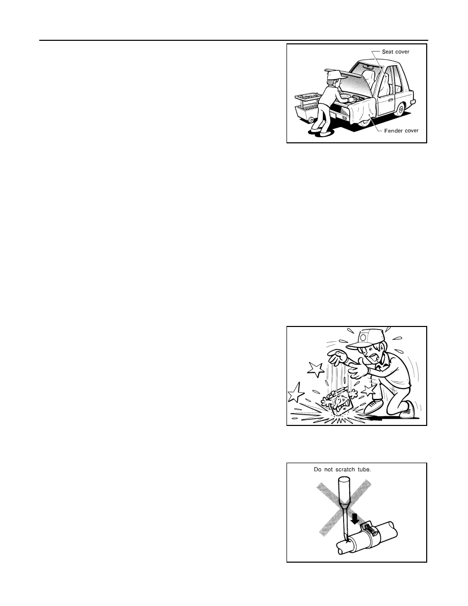
• Before servicing the vehicle:

Protect fenders, upholstery and carpeting with appropriate covers.
Take caution that keys, buckles or buttons do not scratch paint.

WARNING:

To prevent ECM from storing the diagnostic trouble codes, do not carelessly disconnect the harness
connectors which are related to the engine control system and TCM (transmission control module)
system. The connectors should be disconnected only when working according to the WORK FLOW of
TROUBLE DIAGNOSES in EC and AT sections.

Three Way Catalyst

INFOID:0000000003528641

If a large amount of unburned fuel flows into the catalyst, the catalyst temperature will be excessively high. To
prevent this, follow the instructions.
• Use unleaded gasoline only. Leaded gasoline will seriously damage the three way catalyst.
• When checking for ignition spark or measuring engine compression, make tests quickly and only when nec-

essary.

• Do not run engine when the fuel tank level is low, otherwise the engine may misfire, causing damage to the

catalyst.

Do not place the vehicle on flammable material. Keep flammable material off the exhaust pipe and the three
way catalyst.

Multiport Fuel Injection System or Engine Control System

INFOID:0000000003528642

• Before connecting or disconnecting any harness connector for the

multiport fuel injection system or ECM:
Turn ignition switch to “OFF” position.
Disconnect negative battery terminal.
Otherwise, there may be damage to ECM.

• Before disconnecting pressurized fuel line from fuel pump to injec-

tors, be sure to release fuel pressure.

• Be careful not to jar components such as ECM and mass air flow

sensor.

Hoses

INFOID:0000000003528643

HOSE REMOVAL AND INSTALLATION

• To prevent damage to rubber hose, do not pry off rubber hose with

tapered tool or screwdriver.

SGI234

SGI787

SMA019D

Revision: 2008 October

2009 Murano

PRECAUTIONS

GI-29

< PRECAUTION >

C

D

E

F

G

H

I

J

K

L

M

B

GI

N

O

P

• To reinstall the rubber hose securely, make sure that hose insertion

length and orientation is correct. (If tube is equipped with hose
stopper, insert rubber hose into tube until it butts up against hose
stopper.)

HOSE CLAMPING

• If old rubber hose is re-used, install hose clamp in its original posi-

tion (at the indentation where the old clamp was). If there is a trace
of tube bulging left on the old rubber hose, align rubber hose at
that position. 

• Discard old clamps; replace with new ones.

• After installing plate clamps, apply force to them in the direction of

the arrow, tightening rubber hose equally all around.

Engine Oils

INFOID:0000000003528644

Prolonged and repeated contact with used engine oil may cause skin cancer. Try to avoid direct skin contact
with used oil.
If skin contact is made, wash thoroughly with soap or hand cleaner as soon as possible.

HEALTH PROTECTION PRECAUTIONS 

• Avoid prolonged and repeated contact with oils, particularly used engine oils.
• Wear protective clothing, including impervious gloves where practicable.
• Do not put oily rags in pockets.
• Avoid contaminating clothes, particularly underpants, with oil.
• Heavily soiled clothing and oil-impregnated footwear should not be worn. Overalls must be cleaned regu-

larly.

• First aid treatment should be obtained immediately for open cuts and wounds.
• Use barrier creams, applying them before each work period, to help the removal of oil from the skin.
• Wash with soap and water to ensure all oil is removed (skin cleansers and nail brushes will help). Prepara-

tions containing lanolin replace the natural skin oils which have been removed.

• Do not use gasoline, kerosene, diesel fuel, gas oil, thinners or solvents for cleaning skin.
• If skin disorders develop, obtain medical advice without delay.
• Where practical, degrease components prior to handling.
• Where there is a risk of eye contact, eye protection should be worn, for example, chemical goggles or face

shields; in addition an eye wash facility should be provided.

ENVIRONMENTAL PROTECTION PRECAUTIONS 

SMA020D

SMA021D

SMA022D

Revision: 2008 October

2009 Murano

GI-30

< PRECAUTION >

PRECAUTIONS

Dispose of used oil and used oil filters through authorized waste disposal contractors to licensed waste dis-
posal sites, or to the waste oil reclamation trade. If in doubt, contact the local authority for advice on disposal
facilities.
It is illegal to pour used oil on to the ground, down sewers or drains, or into water sources.
The regulations concerning pollution vary between regions.

Air Conditioning

INFOID:0000000003528645

Use an approved refrigerant recovery unit any time the air conditioning system must be discharged. Refer to
HA section “REFRIGERATION SYSTEM” for specific instructions.

Fuel

INFOID:0000000003528646

NISSAN recommends the use of unleaded premium gasoline with an octane rating of at least 91 AKI (Anti-
Knock Index) number (Research octane number 96).

If unleaded premium gasoline is not available, you may use unleaded regular gasoline with an octane rating of
at least 87 AKI number (Research octane number 91), but you may notice a decrease in performance.

CAUTION:

Do not use leaded gasoline. Using leaded gasoline will damage the three way catalyst. Do not use E-85
fuel (85% fuel ethanol, 15% unleaded gasoline) unless the vehicle is specifically designed for E-85 fuel
(i.e. Flexible Fuel Vehicle - FFV models). Using a fuel other than that specified could adversely affect
the emission control devices and systems, and could also affect the warranty coverage validity.

Revision: 2008 October

2009 Murano

LIFTING POINT

GI-31

< PRECAUTION >

C

D

E

F

G

H

I

J

K

L

M

B

GI

N

O

P

LIFTING POINT

Commercial Service Tools

INFOID:0000000003528647

CAUTION:

• Every time the vehicle is lifted up, maintain the complete vehicle curb condition.
• Since the vehicle's center of gravity changes when removing main parts on the front side (engine,

transmission, suspension etc.), support a jack up point on the rear side garage jack with a mission
jack or equivalent. 

• Since the vehicle's center of gravity changes when removing main parts on the rear side (rear axle,

suspension, etc.), support a jack up point on the front side garage jack with a mission jack or equiv-
alent. 

• Be careful not to smash or do not do anything that would affect piping parts.

Garage Jack and Safety Stand and 2-Pole Lift

INFOID:0000000003528648

WARNING:

• Park the vehicle on a level surface when using the jack. Make sure to avoid damaging pipes, tubes,

etc. under the vehicle.

• Never get under the vehicle while it is supported only by the jack. Always use safety stands when

you have to get under the vehicle.

• Place wheel chocks at both front and back of the wheels on the ground.
• When lifting the vehicle, open the lift arms as wide as possible and ensure that the front and rear of

the vehicle are well balanced.

• When setting the lift arm, do not allow the arm to contact the brake tubes, brake cable, fuel lines and

sill spoiler.

Tool name

Description

Board on attachment

Safety stand attachment

S-NT001

S-NT002

Revision: 2008 October

2009 Murano

GI-32

< PRECAUTION >

LIFTING POINT

CAUTION:

There is canister just behind Garage jack point rear. Jack up be carefully.

Board-On Lift

INFOID:0000000003528649

CAUTION:

Make sure vehicle is empty when lifting.

• The board-on lift attachment (A) set at front end of vehicle

should be set on the front of the sill under the front door
opening.

• Position attachments at front and rear ends of board-on lift.

1.

Safety stand point and lift up point (front) 2.

Safety stand point and lift up point 
(rear)

3.

Garage jack point (front)

4.

Garage jack point (rear) (AWD)

5.

Garage jack point (rear) (2WD)

JMAIA0082ZZ

: Vehicle front

JMAIA0004ZZ

Revision: 2008 October

2009 Murano

TOW TRUCK TOWING

GI-33

< PRECAUTION >

C

D

E

F

G

H

I

J

K

L

M

B

GI

N

O

P

TOW TRUCK TOWING

Tow Truck Towing

INFOID:0000000003528650

CAUTION:

• All applicable state or Provincial (in Canada) laws and local laws regarding the towing operation

must be obeyed.

• It is necessary to use proper towing equipment to avoid possible damage to the vehicle during tow-

ing operation. Towing is in accordance with Towing Procedure Manual at dealer.

• Always attach safety chains before towing.
• When towing, make sure that the transmission, steering system and powertrain are in good order. If

any unit is damaged, dollies must be used.

• Never tow a CVT model from the rear (that is backward) with four wheels on the ground. This may

cause serious and expensive damage to the transmission.

2WD MODELS

NISSAN recommends that vehicle be towed with the driving (front) wheels off the ground or that a dolly be
used as illustrated.

CAUTION:

• Never tow CVT models with the front wheels on the ground or four wheels on the ground (forward or

backward), as this may cause serious and expensive damage to the transmission.
If it is necessary to tow the vehicle with the rear wheels raised, always use towing dollies under the
front wheels. 

• When towing CVT models with the front wheels on towing dollies:
- Turn the ignition switch to the OFF position, and secure the steering wheel in a straight ahead posi-

tion with a rope or similar device.Never secure the steering wheel by turning the ignition switch to
the LOCK position. This may damage the steering lock mechanism.

- Move the selector lever to the N (Neutral) position.
• When the battery of vehicle equipped with the Intelligent Key system is discharged, your vehicle

should be towed with the front wheels on towing dollies or place the vehicle on a flat bed truck.

• When towing two wheel drive CVT model with the rear wheels on the ground (if you do not use tow-

ing dollies): Always release the parking brake.

JMAIA0068ZZ

Revision: 2008 October

2009 Murano

GI-34

< PRECAUTION >

TOW TRUCK TOWING

AWD MODELS

NISSAN recommends that a dolly be used as illustrated when towing AWD models.

CAUTION:

Never tow AWD models with any of the wheels on the ground as this may cause serious and expen-
sive damage to the powertrain.

Vehicle Recovery (Freeing a Stuck Vehicle)

INFOID:0000000003528651

FRONT

Securely install the vehicle recovery hook stored with jacking tools.
Make sure that the hook is properly secured in the stored place after
use.

WARNING:

• Stand clear of a stuck vehicle.
• Do not spin your tires at high speed. This could cause them to

explode and result in serious injury. Parts of your vehicle
could also overheat and be damaged.

CAUTION:

• Tow chains or cables must be attached only to the vehicle

recovery hooks or main structural members of the vehicle.
Otherwise, the vehicle body will be damaged.

• Do not use the vehicle tie downs to free a vehicle stuck in sand, snow, mud, etc. Never tow the vehi-

cle using the vehicle tie downs or recovery hooks.

• Always pull the cable straight out from the front of the vehicle. Never pull on the hook at an angle.
• Pulling devices should be routed so they do not touch any part of the suspension, steering, brake or

cooling systems.

• Pulling devices such as ropes or canvas straps are not recommended for use in vehicle towing or

recovery.

REAR

WARNING:

JMAIA0069ZZ

JMAIA0083ZZ

Revision: 2008 October

2009 Murano

TOW TRUCK TOWING

GI-35

< PRECAUTION >

C

D

E

F

G

H

I

J

K

L

M

B

GI

N

O

P

• Rear hook is not available.

AUTOMATIC TRANSMISSION

To tow a vehicle equipped with an automatic transmission, an appropriate vehicle dolly MUST be placed under
the towed vehicle's drive wheels. Always follow the dolly manufacture's recommendations when using their
product.
If the vehicle is stuck in sand, snow, mud, etc., use the following procedure:
1.

Turn off the Vehicle Dynamic Control System.

2.

Make sure the area in front and behind the vehicle is clear of obstructions.

3.

Turn the steering wheel right and left to clear an area around the front tires.

4.

Slowly rock the vehicle forward and backward.
Shift back and forth between R (reverse) and D (drive).
Apply the accelerator as little as possible to maintain the rocking motion.
Release the accelerator pedal before shifting between R and D.
Do not spin the tires above 35 mph (55 km/h).

5.

If the vehicle can not be freed after a few tries, contact a professional towing service to remove the vehi-
cle.

JMAIA0084ZZ

Revision: 2008 October

2009 Murano

GI-36

< BASIC INSPECTION >

SERVICE INFORMATION FOR ELECTRICAL INCIDENT

BASIC INSPECTION

SERVICE INFORMATION FOR ELECTRICAL INCIDENT

Work Flow

INFOID:0000000003528652

WORK FLOW

Control Units and Electrical Parts

INFOID:0000000003528653

PRECAUTIONS

• Never reverse polarity of battery terminals.
• Install only parts specified for a vehicle.
• Before replacing the control unit, check the input and output and functions of the component parts. 
• Do not apply excessive force when disconnecting a connector.

SGI838

STEP

DESCRIPTION

STEP 1

Get detailed information about the conditions and the environment when the incident occurred.
The following are key pieces of information required to make a good analysis:

WHAT

Vehicle Model, Engine, Transmission/Transaxle and the System (i.e. Radio).

WHEN

Date, Time of Day, Weather Conditions, Frequency.

WHERE

Road Conditions, Altitude and Traffic Situation.

HOW

System Symptoms, Operating Conditions (Other Components Interaction). 
Service History and if any After Market Accessories have been installed. 

STEP 2

Operate the system, road test if necessary.
Verify the parameter of the incident.
If the problem cannot be duplicated, refer to “Incident Simulation Tests”.

STEP 3

Get the proper diagnosis materials together including:
• Power Supply Routing
• System Operation Descriptions
• Applicable Service Manual Sections
• Check for any Service Bulletins
Identify where to begin diagnosis based upon your knowledge of the system operation and the customer comments.

STEP 4

Inspect the system for mechanical binding, loose connectors or wiring damage.
Determine which circuits and components are involved and diagnose using the Power Supply Routing and Harness Lay-
outs.

STEP 5

Repair or replace the incident circuit or component.

STEP 6

Operate the system in all modes. Verify the system works properly under all conditions. Make sure you have not inad-
vertently created a new incident during your diagnosis or repair steps.

Revision: 2008 October

2009 Murano

SERVICE INFORMATION FOR ELECTRICAL INCIDENT

GI-37

< BASIC INSPECTION >

C

D

E

F

G

H

I

J

K

L

M

B

GI

N

O

P

• Do not apply excessive shock to the control unit by dropping or hit-

ting it.

• Be careful to prevent condensation in the control unit due to rapid

temperature changes and do not let water or rain get on it. If water
is found in the control unit, dry it fully and then install it in the vehi-
cle.

• Be careful not to let oil to get on the control unit connector.
• Avoid cleaning the control unit with volatile oil.
• Do not disassemble the control unit, and do not remove the upper

and lower covers.

• When using a DMM, be careful not to let test probes get close to

each other to prevent the power transistor in the control unit from
damaging battery voltage because of short circuiting.

• When checking input and output signals of the control unit, use the

specified check adapter.

How to Check Terminal

INFOID:0000000003528654

CONNECTOR AND TERMINAL PIN KIT

• Use the connector and terminal pin kits listed below when replacing connectors or terminals.
• The connector and terminal pin kits contain some of the most commonly used NISSAN/INFINITI connectors

and terminals. For detailed connector and terminal pin replacement procedures, refer to the latest NISSAN/
INFINITI CONNECTOR AND TERMINAL PIN SERVICE MANUAL.

SAIA0255E

SEF348N

Revision: 2008 October

2009 Murano

GI-38

< BASIC INSPECTION >

SERVICE INFORMATION FOR ELECTRICAL INCIDENT

HOW TO PROBE CONNECTORS

• Connector damage and an intermittent connection can result from improperly probing of the connector dur-

ing circuit checks.

• The probe of a digital multimeter (DMM) may not correctly fit the connector cavity. To correctly probe the

connector, follow the procedures below using a “T” pin. For the best contact grasp the “T” pin using an alliga-
tor clip.

Probing from Harness Side 

Standard type (not waterproof type) connector should be probed
from harness side with “T” pin.
• If the connector has a rear cover such as a ECM connector,

remove the rear cover before probing the terminal.

• Do not probe waterproof connector from harness side. Damage to

the seal between wire and connector may result.

Probing from Terminal Side 

FEMALE TERMINAL

• There is a small notch above each female terminal. Probe each

terminal with the “T” pin through the notch.
Do not insert any object other than the same type male terminal
into female terminal.

Tool number

(Kent-Moore No.)

Tool name

Description

-
(J38751-95NI)
Connector and terminal 
pin kit (NISSAN)
-
(J38751-95INF)
Connector and terminal 
pin kit (INFINITI) 
-
(J42992-98KIT)
OBD and terminal repair 
kit
-
(J42992-2000UPD)
OBD-II Connector Kit Up-
date

WAIA0004E

WAIA0005E

SGI841

SEL265V

Revision: 2008 October

2009 Murano

SERVICE INFORMATION FOR ELECTRICAL INCIDENT

GI-39

< BASIC INSPECTION >

C

D

E

F

G

H

I

J

K

L

M

B

GI

N

O

P

• Some connectors do not have a notch above each terminal. To

probe each terminal, remove the connector retainer to make con-
tact space for probing.

MALE TERMINAL

• Carefully probe the contact surface of each terminal using a “T”

pin.

CAUTION:

Dot not bend terminal.

How to Check Enlarged Contact Spring of Terminal

• An enlarged contact spring of a terminal may create intermittent signals in the circuit.
• If the intermittent open circuit occurs, follow the procedure below to inspect for open wires and enlarged con-

tact spring of female terminal.

1.

Assemble a male terminal and approx. 10 cm (3.9 in) of wire.
NOTE:
Use a male terminal which matches the female terminal.

2.

Disconnect the suspected faulty connector and hold it terminal
side up.

3.

While holding the wire of the male terminal, try to insert the male
terminal into the female terminal.

CAUTION:

Do not force the male terminal into the female terminal with
your hands.

SEL266V

SEL267V

SEL270V

SEL271V

Revision: 2008 October

2009 Murano

GI-40

< BASIC INSPECTION >

SERVICE INFORMATION FOR ELECTRICAL INCIDENT

4.

While moving the connector, check whether the male terminal
can be easily inserted or not.

• If the male terminal can be easily inserted into the female ter-

minal, replace the female terminal.

Waterproof Connector Inspection 

If water enters the connector, it can short interior circuits. This may lead to intermittent problems.
Check the following items to maintain the original waterproof characteristics.

RUBBER SEAL INSPECTION

• Most waterproof connectors are provided with a rubber seal

between the male and female connectors. If the seal is missing,
the waterproof performance may not meet specifications.

• The rubber seal may come off when connectors are disconnected.

Whenever connectors are reconnected, make sure the rubber seal
is properly installed on either side of male or female connector.

WIRE SEAL INSPECTION

• The wire seal must be installed on the wire insertion area of a

waterproof connector. Be sure that the seal is installed properly.

Terminal Lock Inspection 

Check for unlocked terminals by pulling wire at the end of connector.
An unlocked terminal may create intermittent signals in the circuit.

Intermittent Incident

INFOID:0000000003528655

DESCRIPTION

Sometimes the symptom is not present when the vehicle is brought in for service. If possible, re-create the
conditions present at the time of the incident. Doing so may help avoid a No Trouble Found Diagnosis. The fol-

SEL272V

SEL273V

SEL275V

SEL330V

Revision: 2008 October

2009 Murano

SERVICE INFORMATION FOR ELECTRICAL INCIDENT

GI-41

< BASIC INSPECTION >

C

D

E

F

G

H

I

J

K

L

M

B

GI

N

O

P

lowing section illustrates ways to simulate the conditions/environment under which the owner experiences an
electrical incident.

The section is broken into the six following topics:

• Vehicle vibration
• Heat sensitive
• Freezing
• Water intrusion
• Electrical load
• Cold or hot start up
Get a thorough description of the incident from the customer. It is important for simulating the conditions of the
problem.

VEHICLE VIBRATION

The problem may occur or become worse while driving on a rough road or when engine is vibrating (idle with
A/C on). In such a case, you will want to check for a vibration related condition. Refer to the following illustra-
tion.

Connector & Harness

Determine which connectors and wiring harness would affect the electrical system you are inspecting. Gently
shake each connector and harness while monitoring the system for the incident you are trying to duplicate.
This test may indicate a loose or poor electrical connection.

Hint

Connectors can be exposed to moisture. It is possible to get a thin film of corrosion on the connector termi-
nals. A visual inspection may not reveal this without disconnecting the connector. If the problem occurs inter-
mittently, perhaps the problem is caused by corrosion. It is a good idea to disconnect, inspect and clean the
terminals on related connectors in the system.

Sensor & Relay

Gently apply a slight vibration to sensors and relays in the system you are inspecting.
This test may indicate a loose or poorly mounted sensor or relay.

Engine Compartment

There are several reasons a vehicle or engine vibration could cause an electrical complaint. Some of the
things to check for are:
• Connectors not fully seated.
• Wiring harness not long enough and is being stressed due to engine vibrations or rocking.
• Wires laying across brackets or moving components.
• Loose, dirty or corroded ground wires.
• Wires routed too close to hot components.
To inspect components under the hood, start by verifying the integrity of ground connections. (Refer to Ground
Inspection described later.) First check that the system is properly grounded. Then check for loose connection
by gently shaking the wiring or components as previously explained. Using the wiring diagrams inspect the
wiring for continuity.

Behind the Instrument Panel

An improperly routed or improperly clamped harness can become pinched during accessory installation. Vehi-
cle vibration can aggravate a harness which is routed along a bracket or near a screw.

Under Seating Areas

SGI839

Revision: 2008 October

2009 Murano

GI-42

< BASIC INSPECTION >

SERVICE INFORMATION FOR ELECTRICAL INCIDENT

An unclamped or loose harness can cause wiring to be pinched by seat components (such as slide guides)
during vehicle vibration. If the wiring runs under seating areas, inspect wire routing for possible damage or
pinching.

HEAT SENSITIVE

• The customer's concern may occur during hot weather or after car

has sat for a short time. In such cases you will want to check for a
heat sensitive condition.

• To determine if an electrical component is heat sensitive, heat the

component with a heat gun or equivalent.

CAUTION:

Do not heat components above 60

°

C (140

°

).

• If incident occurs while heating the unit, either replace or properly

insulate the component.

FREEZING 

• The customer may indicate the incident goes away after the car

warms up (winter time). The cause could be related to water freez-
ing somewhere in the wiring/electrical system.

• There are two methods to check for this. The first is to arrange for

the owner to leave his car overnight. Make sure it will get cold
enough to demonstrate his complaint. Leave the car parked out-
side overnight. In the morning, do a quick and thorough diagnosis
of those electrical components which could be affected.

• The second method is to put the suspect component into a freezer

long enough for any water to freeze. Reinstall the part into the car
and check for the reoccurrence of the incident. If it occurs, repair or
replace the component.

WATER INTRUSION

The incident may occur only during high humidity or in rainy/snowy
weather. In such cases the incident could be caused by water intru-
sion on an electrical part. This can be simulated by soaking the car
or running it through a car wash.

CAUTION:

Do not spray water directly on any electrical components.

ELECTRICAL LOAD 

The incident may be electrical load sensitive. Perform diagnosis with
all accessories (including A/C, rear window defogger, radio, fog
lamps) turned on.

COLD OR HOT START UP 

On some occasions an electrical incident may occur only when the car is started cold, or it may occur when
the car is restarted hot shortly after being turned off. In these cases you may have to keep the car overnight to
make a proper diagnosis.

SGI842

SGI843

SGI844

SGI845

Revision: 2008 October

2009 Murano

SERVICE INFORMATION FOR ELECTRICAL INCIDENT

GI-43

< BASIC INSPECTION >

C

D

E

F

G

H

I

J

K

L

M

B

GI

N

O

P

Circuit Inspection

INFOID:0000000003528656

DESCRIPTION 

• In general, testing electrical circuits is an easy task if it is approached in a logical and organized method.

Before beginning it is important to have all available information on the system to be tested. Also, get a thor-
ough understanding of system operation. Then you will be able to use the appropriate equipment and follow
the correct test procedure.

• You may have to simulate vehicle vibrations while testing electrical components. Gently shake the wiring

harness or electrical component to do this.

NOTE:
Refer to 

GI-37, "How to Check Terminal"

 to probe or check terminal.

TESTING FOR “OPENS” IN THE CIRCUIT

Before you begin to diagnose and test the system, you should rough sketch a schematic of the system. This
will help you to logically walk through the diagnosis process. Drawing the sketch will also reinforce your work-
ing knowledge of the system.

Continuity Check Method

The continuity check is used to find an open in the circuit. The digital multimeter (DMM) set on the resistance
function will indicate an open circuit as over limit (no beep tone or no ohms symbol). Make sure to always start
with the DMM at the highest resistance level. 
To help in understanding the diagnosis of open circuits, please refer to the previous schematic.
• Disconnect the battery negative cable.
• Start at one end of the circuit and work your way to the other end. (At the fuse block in this example)
• Connect one probe of the DMM to the fuse block terminal on the load side.
• Connect the other probe to the fuse block (power) side of SW1. Little or no resistance will indicate that por-

tion of the circuit has good continuity. If there were an open in the circuit, the DMM would indicate an over
limit or infinite resistance condition. (point A)

• Connect the probes between SW1 and the relay. Little or no resistance will indicate that portion of the circuit

has good continuity. If there were an open in the circuit, the DMM would indicate an over limit or infinite resis-
tance condition. (point B)

• Connect the probes between the relay and the solenoid. Little or no resistance will indicate that portion of the

circuit has good continuity. If there were an open in the circuit, the DMM would indicate an over limit or infi-
nite resistance condition. (point C)

Any circuit can be diagnosed using the approach in the previous example.

Voltage Check Method

To help in understanding the diagnosis of open circuits please refer to the previous schematic.
In any powered circuit, an open can be found by methodically checking the system for the presence of voltage.
This is done by switching the DMM to the voltage function.
• Connect one probe of the DMM to a known good ground.
• Begin probing at one end of the circuit and work your way to the other end.
• With SW1 open, probe at SW1 to check for voltage.

voltage; open is further down the circuit than SW1.

OPEN

A circuit is open when there is no continuity through a section of the circuit.

SHORT

There are two types of shorts.

• SHORT CIRCUIT

When a circuit contacts another circuit and causes the normal resistance to 
change.

• SHORT TO GROUND

When a circuit contacts a ground source and grounds the circuit.

SGI846-A

Revision: 2008 October

2009 Murano


Content      ..     211      212      213      214     ..