Nissan Murano Z51 (2008 year). Manual - part 212


  Index      Manuals     Nissan Murano Z51 (2008 year) - Service and Repair Manual


Search            copyright infringement  


Content      ..     210      211      212      213     ..


Nissan Murano Z51 (2008 year). Manual - part 212


GI-12

< HOW TO USE THIS MANUAL >

HOW TO READ WIRING DIAGRAMS

• ignition switch is “OFF”,
• doors, hood and trunk lid/back door are closed,
• pedals are not depressed, and
• parking brake is released.
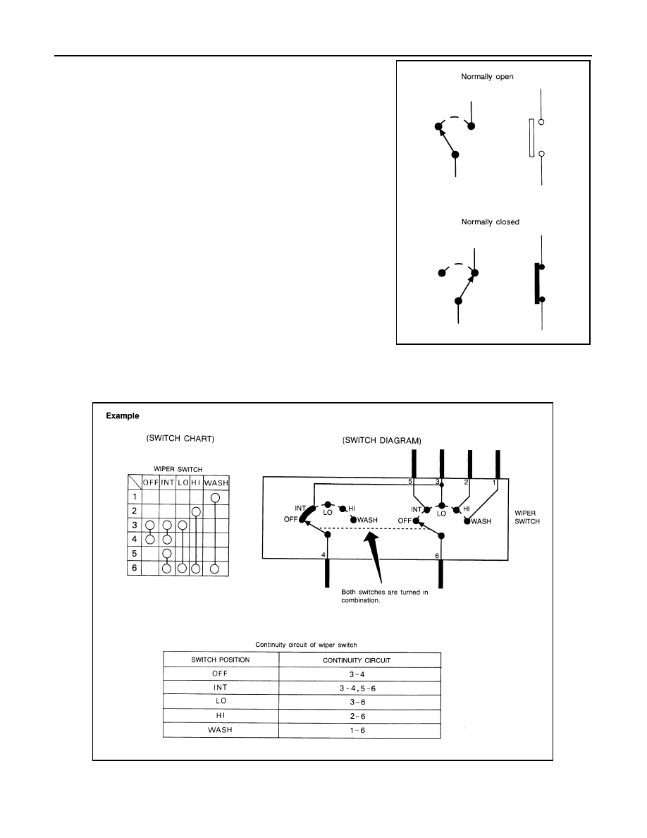
MULTIPLE SWITCH

The continuity of multiple switch is described in two ways as shown below.
• The switch chart is used in schematic diagrams.
• The switch diagram is used in wiring diagrams.

SGI860

JSAIA0017GB

Revision: 2008 October

2009 Murano

ABBREVIATIONS

GI-13

< HOW TO USE THIS MANUAL >

C

D

E

F

G

H

I

J

K

L

M

B

GI

N

O

P

ABBREVIATIONS

Abbreviation List

INFOID:0000000003528621

The following ABBREVIATIONS are used:

ABBREVIATION

DESCRIPTION

A/C

Air Conditioner

A/T

Automatic Transaxle/Transmission

ATF

Automatic Transmission Fluid

D

1

Drive range 1st gear

D

2

Drive range 2nd gear

D

3

Drive range 3rd gear

D

4

Drive range 4th gear

FR, RR

Front, Rear

LH, RH

Left-Hand, Right-Hand

M/T

Manual Transaxle/Transmission

OD

Overdrive

P/S

Power Steering

SAE

Society of Automotive Engineers, Inc.

SDS

Service Data and Specifications

SST

Special Service Tools

2WD

2-Wheel Drive

2

2

2nd range 2nd gear

2

1

2nd range 1st gear

1

2

1st range 2nd gear

1

1

1st range 1st gear

Revision: 2008 October

2009 Murano

GI-14

< HOW TO USE THIS MANUAL >

TIGHTENING TORQUE OF STANDARD BOLTS

TIGHTENING TORQUE OF STANDARD BOLTS

Description

INFOID:0000000003528622

This vehicle has both new standard based on ISO* and previous standard bolts/nuts. There are some differ-
ences between these two types of bolts/ nuts; shape of the head, grade of strength, hexagonal width across
flats and the standard tightening torque.
• For guidance in discriminating, refer to 

GI-14, "Tightening Torque Table (New Standard Included)"

.

• The new standard machine screws and tapping screws have a head of ISO standard torx recess.
• If the tightening torque is not described in the description or figure, refer to 

GI-14, "Tightening Torque Table

(New Standard Included)"

.

*ISO: International Organization for Standardization

Tightening Torque Table (New Standard Included)

INFOID:0000000003528623

CAUTION:

• The special parts are excluded.
• The bolts/nuts in these tables have a strength (discrimination) number/symbol assigned to the head

or the like. As to the relation between the strength grade in these tables and the strength (discrimi-
nation) number/symbol, refer to “DISCRIMINATION OF BOLTS AND NUTS”.

PREVIOUS STANDARD

CAUTION:

Grade 

(Strength 

grade)

Bolt 
size

Bolt di-
ameter

mm

Hexagonal 

width 

across flats

mm

Pitch

mm

Tightening torque (Without lubricant)

Hexagon head bolt

Hexagon flange bolt

N·m

kg-m

ft-lb

in-lb

N·m

kg-m

ft-lb

in-lb

4T

M6

6.0

10

1.0

5.5

0.56

4

49

7

0.71

5

62

M8

8.0

12

1.25

13.5

1.4

10

17

1.7

13

1.0

13.5

1.4

10

17

1.7

13

M10

10.0

14

1.5

28

2.9

21

35

3.6

26

1.25

28

2.9

21

35

3.6

26

M12

12.0

17

1.75

45

4.6

33

55

5.6

41

1.25

45

4.6

33

65

6.6

48

M14

14.0

19

1.5

80

8.2

59

100

10

74

7T

M6

6.0

10

1.0

9

0.92

7

80

11

1.1

8

97

M8

8.0

12

1.25

22

2.2

16

28

2.9

21

1.0

22

2.2

16

28

2.9

21

M10

10.0

14

1.5

45

4.6

33

55

5.6

41

1.25

45

4.6

33

55

5.6

41

M12

12.0

17

1.75

80

8.2

59

100

10

74

1.25

80

8.2

59

100

10

74

M14

14.0

19

1.5

130

13

96

170

17

125

9T

M6

6.0

10

1.0

11

1.1

8

13.5

1.4

10

M8 8.0

12

1.25

28

2.9

21

35

3.6

26

1.0

28

2.9

21

35

3.6

26

M10

10.0

14

1.5

55

5.6

41

80

8.2

59

1.25

55

5.6

41

80

8.2

59

M12

12.0

17

1.75

100

10

74

130

13

96

1.25

100

10

74

130

13

96

M14

14.0

19

1.5

170

17

125

210

21

155

Revision: 2008 October

2009 Murano

TIGHTENING TORQUE OF STANDARD BOLTS

GI-15

< HOW TO USE THIS MANUAL >

C

D

E

F

G

H

I

J

K

L

M

B

GI

N

O

P

The parts with aluminum or the cast iron washer surface/thread surface are excluded.

NEW STANDARD BASED ON ISO

CAUTION:

1.

Use tightening torque with lubricant for the new standard bolts/nuts in principle. Friction coeffi-
cient stabilizer is applied to the new standard bolts/nuts.

2.

However, use tightening torque without lubricant for the following cases. Friction coefficient stabi-
lizer is not applied to the following bolts/nuts.

-

Grade 4.8, M6 size bolt, Conical spring washer installed

-

Paint removing nut (Size M6 and M8) for fixing with weld bolt

Grade 

(Strength 

grade)

Bolt 
size

Bolt di-
ameter

mm

Hexagonal 

width 

across flats

mm

Pitch

mm

Tightening torque

Hexagon head bolt

Hexagon flange bolt

N·m

kg-m

ft-lb

in-lb

N·m

kg-m

ft-lb

in-lb

4.8
(Without 
lubricant)

M6

6.0

10

1.0

5.5

0.56

4

49

7

0.71

5

62

M8

8.0

13

1.25

13.5

1.4

10

17

1.7

13

1.0

13.5

1.4

10

17

1.7

13

M10

10.0

16

1.5

28

2.9

21

35

3.6

26

1.25

28

2.9

21

35

3.6

26

M12

12.0

18

1.75

45

4.6

33

55

5.6

41

1.25

45

4.6

33

65

6.6

48

M14

14.0

21

1.5

80

8.2

59

100

10

74

4.8
(With lu-
bricant)

M6

6.0

10

1.0

4

0.41

3

35

5.5

0.56

4

49

M8

8.0

13

1.25

11

1.1

8

13.5

1.4

10

1.0

11

1.1

8

13.5

1.4

10

M10

10.0

16

1.5

22

2.2

16

28

2.9

21

1.25

22

2.2

16

28

2.9

21

M12

12.0

18

1.75

35

3.6

26

45

4.6

33

1.25

35

3.6

26

45

4.6

33

M14

14.0

21

1.5

65

6.6

48

80

8.2

59

8.8
(With lu-
bricant)

M6

6.0

10

1.0

8

0.82

6

71

10

1.0

7

89

M8

8.0

13

1.25

21

2.1

15

25

2.6

18

1.0

21

2.1

15

25

2.6

18

M10

10.0

16

1.5

40

4.1

30

50

5.1

37

1.25

40

4.1

30

50

5.1

37

M12

12.0

18

1.75

70

7.1

52

85

8.7

63

1.25

70

7.1

52

85

8.7

63

M14

14.0

21

1.5

120

12

89

140

14

103

10.9
(With lu-
bricant)

M6

6.0

10

1.0

10

1.0

7

89

12

1.2

9

106

M8

8.0

13

1.25

27

2.8

20

32

3.3

24

1.0

27

2.8

20

32

3.3

24

M10

10.0

16

1.5

55

5.6

41

65

6.6

48

1.25

55

5.6

41

65

6.6

48

M12

12.0

18

1.75

95

9.7

70

110

11

81

1.25

95

9.7

70

110

11

81

M14

14.0

21

1.5

160

16

118

180

18

133

Revision: 2008 October

2009 Murano

GI-16

< HOW TO USE THIS MANUAL >

TIGHTENING TORQUE OF STANDARD BOLTS

DISCRIMINATION OF BOLTS AND NUTS

SAIA0453E

Revision: 2008 October

2009 Murano

RECOMMENDED CHEMICAL PRODUCTS AND SEALANTS

GI-17

< HOW TO USE THIS MANUAL >

C

D

E

F

G

H

I

J

K

L

M

B

GI

N

O

P

RECOMMENDED CHEMICAL PRODUCTS AND SEALANTS

Recommended Chemical Products and Sealants

INFOID:0000000003528624

Refer to the following chart for help in selecting the appropriate chemical product or sealant.

Product Description

Purpose

Nissan North America 

Part No. (USA)

Nissan Canada Part 

No. (Canada)

Aftermarket Cross-

reference Part Nos.

1

Rear View Mirror Adhe-
sive

Used to permanently re-
mount rear view mirrors to 
windows.

999MP-AM000P

99998-50505

Permatex 81844

2

Anaerobic Liquid Gas-
ket

For metal-to-metal flange 
sealing.
Can fill a 0.38 mm (0.015 
inch) gap and provide in-
stant sealing for most pow-
ertrain applications.

999MP-AM001P

99998-50503

Permatex 51813 and 
51817

3

High Performance 
Thread Sealant

Provides instant sealing on 
any threaded straight or 
parallel threaded fitting. 
(Thread sealant only, no 
locking ability.)
• Do not use on plastic.

999MP-AM002P

999MP-AM002P

Permatex 56521

4

Silicone RTV

Gasket Maker

999MP-AM003P
(Ultra Grey)

99998-50506
(Ultra Grey)

Permatex Ultra Grey 
82194;
Three Bond 
1207,1215, 1216, 
1217F, 1217G and 
1217H
Nissan RTV Part No. 
999MP-A7007

Gasket Maker for Maxima/
Quest 5-speed automatic 
transmission
(RE5F22A)

Three Bond 1281B 
or exact equivalent in 
its quality

5

High Temperature, 
High Strength Thread 
Locking Sealant (Red)

Threadlocker

999MP-AM004P

999MP-AM004P

Permatex 27200;
Three Bond 1360, 
1360N, 1305 N&P, 
1307N, 1335, 
1335B, 1363B, 
1377C, 1386B, D&E 
and 1388
Loctite 648

6

Medium Strength 
Thread Locking Seal-
ant (Blue)

Threadlocker (service tool 
removable)

999MP-AM005P

999MP-AM005P

Permatex 24200, 
24206, 24240, 
24283 and 09178;
Three Bond 1322, 
1322N, 1324 D&N, 
1333D, 1361C, 
1364D, 1370C and 
1374

Revision: 2008 October

2009 Murano

GI-18

< HOW TO USE THIS MANUAL >

TERMINOLOGY

TERMINOLOGY

SAE J1930 Terminology List

INFOID:0000000003528625

All emission related terms used in this publication in accordance with SAE J1930 are listed. Accordingly, new
terms, new acronyms/abbreviations and old terms are listed in the following chart.

NEW TERM

NEW ACRONYM /

ABBREVIATION

OLD TERM

Air cleaner

ACL

Air cleaner

Barometric pressure

BARO

***

Barometric pressure sensor-BCDD

BAROS-BCDD

BCDD

Camshaft position

CMP

***

Camshaft position sensor

CMPS

Crank angle sensor

Canister

***

Canister

Carburetor

CARB

Carburetor

Charge air cooler

CAC

Intercooler

Closed loop

CL

Closed loop

Closed throttle position switch

CTP switch

Idle switch

Clutch pedal position switch

CPP switch

Clutch switch

Continuous fuel injection system

CFI system

***

Continuous trap oxidizer system

CTOX system

***

Crankshaft position

CKP

***

Crankshaft position sensor

CKPS

***

Data link connector

DLC

***

Diagnostic test mode

DTM

Diagnostic mode

Diagnostic test mode selector

DTM selector

Diagnostic mode selector

Diagnostic test mode I

DTM I

Mode I

Diagnostic test mode II

DTM II

Mode II

Diagnostic trouble code

DTC

Malfunction code

Direct fuel injection system

DFI system

***

Distributor ignition system

DI system

Ignition timing control

Early fuel evaporation-mixture heater

EFE-mixture heater

Mixture heater

Early fuel evaporation system

EFE system

Mixture heater control

Electrically erasable programmable read 
only memory

EEPROM

***

Electronic ignition system

EI system

Ignition timing control

Engine control

EC

***

Engine control module

ECM

ECCS control unit

Engine coolant temperature

ECT

Engine temperature

Engine coolant temperature sensor

ECTS

Engine temperature sensor

Engine modification

EM

***

Engine speed

RPM

Engine speed

Erasable programmable read only memory

EPROM

***

Evaporative emission canister

EVAP canister

Canister

Evaporative emission system

EVAP system

Canister control solenoid valve

Exhaust gas recirculation valve

EGR valve

EGR valve 

Revision: 2008 October

2009 Murano

TERMINOLOGY

GI-19

< HOW TO USE THIS MANUAL >

C

D

E

F

G

H

I

J

K

L

M

B

GI

N

O

P

Exhaust gas recirculation control-BPT 
valve

EGRC-BPT valve

BPT valve

Exhaust gas recirculation control-solenoid 
valve

EGRC-solenoid valve

EGR control solenoid valve

Exhaust gas recirculation temperature sen-
sor

EGRT sensor

Exhaust gas temperature sensor

EGR temperature sensor

Flash electrically erasable programmable 
read only memory

FEEPROM

***

Flash erasable programmable read only 
memory

FEPROM

***

Flexible fuel sensor

FFS

***

Flexible fuel system

FF system

***

Fuel pressure regulator

***

Pressure regulator

Fuel pressure regulator control solenoid 
valve

***

PRVR control solenoid valve

Fuel trim

FT

***

Heated Oxygen sensor

HO2S

Exhaust gas sensor

Idle air control system

IAC system

Idle speed control

Idle air control valve-air regulator

IACV-air regulator

Air regulator

Idle air control valve-auxiliary air control 
valve

IACV-AAC valve

Auxiliary air control (AAC) valve

Idle air control valve-FICD solenoid valve

IACV-FICD solenoid valve

FICD solenoid valve

Idle air control valve-idle up control sole-
noid valve

IACV-idle up control solenoid valve

Idle up control solenoid valve

Idle speed control-FI pot

ISC-FI pot

FI pot

Idle speed control system

ISC system

***

Ignition control

IC

***

Ignition control module

ICM

***

Indirect fuel injection system

IFI system

***

Intake air

IA

Air

Intake air temperature sensor

IAT sensor

Air temperature sensor

Knock

***

Detonation

Knock sensor

KS

Detonation sensor

Malfunction indicator lamp

MIL

Check engine light

Manifold absolute pressure

MAP

***

Manifold absolute pressure sensor

MAPS

***

Manifold differential pressure

MDP

***

Manifold differential pressure sensor

MDPS

***

Manifold surface temperature

MST

*** 

Manifold surface temperature sensor

MSTS

***

Manifold vacuum zone

MVZ

***

Manifold vacuum zone sensor

MVZS

***

Mass air flow sensor

MAFS

Air flow meter

Mixture control solenoid valve

MC solenoid valve

Air-fuel ratio control solenoid valve

Multiport fuel injection system

MFI system

Fuel injection control

NEW TERM

NEW ACRONYM /

ABBREVIATION

OLD TERM

Revision: 2008 October

2009 Murano

GI-20

< HOW TO USE THIS MANUAL >

TERMINOLOGY

Nonvolatile random access memory

NVRAM

***

On board diagnostic system

OBD system

Self-diagnosis

Open loop

OL

Open loop

Oxidation catalyst

OC

Catalyst 

Oxidation catalytic converter system

OC system

***

Oxygen sensor

O2S

Exhaust gas sensor

Park position switch

***

Park switch

Park/neutral position switch

PNP switch

Park/neutral switch
Inhibitor switch
Neutral position switch

Periodic trap oxidizer system

PTOX system

***

Positive crankcase ventilation

PCV

Positive crankcase ventilation

Positive crankcase ventilation valve

PCV valve

PCV valve

Powertrain control module

PCM

***

Programmable read only memory

PROM

***

Pulsed secondary air injection control sole-
noid valve

PAIRC solenoid valve

AIV control solenoid valve

Pulsed secondary air injection system

PAIR system

Air induction valve (AIV) control

Pulsed secondary air injection valve

PAIR valve

Air induction valve

Random access memory

RAM

***

Read only memory

ROM

***

Scan tool

ST

***

Secondary air injection pump

AIR pump

***

Secondary air injection system

AIR system

***

Sequential multiport fuel injection system

SFI system

Sequential fuel injection

Service reminder indicator

SRI

***

Simultaneous multiport fuel injection sys-
tem

***

Simultaneous fuel injection

Smoke puff limiter system

SPL system

***

Supercharger

SC

***

Supercharger bypass

SCB

***

System readiness test

SRT

***

Thermal vacuum valve

TVV

Thermal vacuum valve

Three way catalyst

TWC

Catalyst

Three way catalytic converter system

TWC system

***

Three way + oxidation catalyst

TWC + OC

Catalyst

Three way + oxidation catalytic converter 
system

TWC + OC system

*** 

Throttle body

TB

Throttle chamber
SPI body

Throttle body fuel injection system

TBI system

Fuel injection control

Throttle position

TP

Throttle position

Throttle position sensor

TPS

Throttle sensor

Throttle position switch

TP switch

Throttle switch

Torque converter clutch solenoid valve

TCC solenoid valve

Lock-up cancel solenoid
Lock-up solenoid

NEW TERM

NEW ACRONYM /

ABBREVIATION

OLD TERM

Revision: 2008 October

2009 Murano

TERMINOLOGY

GI-21

< HOW TO USE THIS MANUAL >

C

D

E

F

G

H

I

J

K

L

M

B

GI

N

O

P

***: Not applicable

Transmission control module

TCM

A/T control unit

Turbocharger

TC

Turbocharger

Vehicle speed sensor

VSS

Vehicle speed sensor

Volume air flow sensor

VAFS

Air flow meter 

Warm up oxidation catalyst

WU-OC

Catalyst

Warm up oxidation catalytic converter sys-
tem

WU-OC system

***

Warm up three way catalyst

WU-TWC

Catalyst

Warm up three way catalytic converter sys-
tem

WU-TWC system

***

Wide open throttle position switch

WOTP switch

Full switch

NEW TERM

NEW ACRONYM /

ABBREVIATION

OLD TERM

Revision: 2008 October

2009 Murano

GI-22

< FEATURES OF NEW MODEL >

IDENTIFICATION INFORMATION

FEATURES OF NEW MODEL

IDENTIFICATION INFORMATION

Model Variation

INFOID:0000000003528626

Model variation code (Prefix and suffix designations)

Destination

Body

Transmission

Engine

Axle

Handle

Grade

Model

USA (Federal)

Wagon

CVT

VQ35DE

AWD (4WD)

LHD

S

TLJNLQZ-EUA

SL

TLJNLTZ-EUA

LE

TLJNLVZ-EUA

2WD

S

TLJALQZ-EUA

SL

TLJALTZ-EUA

AWD (4WD)

SL with moonroof

TLJNLUZ-EUA

LE with moonroof

TLJNLYZ-EUA

2WD

SL with moonroof

TLJALUZ-EUA

California

AWD (4WD)

S

TLJNLQZ-EVA

SL

TLJNLTZ-EVA

SL with moonroof

TLJNLUZ-EVA

LE

TLJNLVZ-EVA

LE with moonroof

TLJNLYZ-EVA

2WD

S

TLJALQZ-EVA

SL

TLJALTZ-EVA

SL with moonroof

TLJALUZ-EVA

Canada

AWD (4WD)

S

TLJNLQZ-ENA

SL

TLJNLTZ-ENA

LE

TLJNLVZ-ENA

SL with moonroof

TLJNLUZ-ENA

LE with moonroof

TLJNLYZ-ENA

Mexico

2WD

S

TLJALQZ-EJA

SL

TLJALTZ-EJA

AWD (4WD)

SL with moonroof

TLJNLUZ-EJA

JPAIA0483GB

Revision: 2008 October

2009 Murano

IDENTIFICATION INFORMATION

GI-23

< FEATURES OF NEW MODEL >

C

D

E

F

G

H

I

J

K

L

M

B

GI

N

O

P

Information About Identification or Model Code

INFOID:0000000003528627

IDENTIFICATION NUMBER

VEHICLE IDENTIFICATION NUMBER ARRANGEMENT

ENGINE SERIAL NUMBER 

JPAIA0261ZZ

1.

Emission control information label
(if equipped)

2. Vehicle identification number (Chas-

sis number)

3.

Vehicle identification number plate

4.

Air conditioner specification label

5. Tire and loading information label

(Tire placard)

6.

FMVSS certification label (if equipped)

JPAIA0496GB

: Vehicle front

JPAIA0388ZZ

Revision: 2008 October

2009 Murano

GI-24

< FEATURES OF NEW MODEL >

IDENTIFICATION INFORMATION

AUTOMATIC TRANSMISSION NUMBER 

Dimensions

INFOID:0000000003528628

Unit: mm (in)

*: With roof rail

Wheels & Tires

INFOID:0000000003528630

: Vehicle front

JPAIA0389ZZ

Overall length

4,788 (188.5)

Overall width

1,883 (74.1)

Overall height

1,703 (67.0), 1,729 (68.1)*

Front tread

1,610 (63.4)

Rear tread

1,610 (63.4)

Wheelbase

2,825 (111.2)

Application

Conventional

Spare

Road wheel/offset

mm (in)

18 

×

 7-1/2JJ Aluminum/50 (1.97)

20 

×

 7-1/2JJ Aluminum/50 (1.97)

18 

×

 4T Steel/25 (0.98)

Tire size

P235/65R18
P235/55R20

T165/90D18

Revision: 2008 October

2009 Murano

PRECAUTIONS

GI-25

< PRECAUTION >

C

D

E

F

G

H

I

J

K

L

M

B

GI

N

O

P

PRECAUTION

PRECAUTIONS

Description

INFOID:0000000003528631

Observe the following precautions to ensure safe and proper servicing. These precautions are not
described in each individual section.

Precaution for Supplemental Restraint System (SRS) "AIR BAG" and "SEAT BELT 
PRE-TENSIONER"

INFOID:0000000004732428

The Supplemental Restraint System such as “AIR BAG” and “SEAT BELT PRE-TENSIONER”, used along
with a front seat belt, helps to reduce the risk or severity of injury to the driver and front passenger for certain
types of collision. This system includes seat belt switch inputs and dual stage front air bag modules. The SRS
system uses the seat belt switches to determine the front air bag deployment, and may only deploy one front
air bag, depending on the severity of a collision and whether the front occupants are belted or unbelted.
Information necessary to service the system safely is included in the “SRS AIRBAG” and “SEAT BELT” of this
Service Manual.

WARNING:

• To avoid rendering the SRS inoperative, which could increase the risk of personal injury or death in

the event of a collision which would result in air bag inflation, all maintenance must be performed by
an authorized NISSAN/INFINITI dealer.

• Improper maintenance, including incorrect removal and installation of the SRS, can lead to personal

injury caused by unintentional activation of the system. For removal of Spiral Cable and Air Bag
Module, see the “SRS AIRBAG”.

• Never use electrical test equipment on any circuit related to the SRS unless instructed to in this Ser-

vice Manual. SRS wiring harnesses can be identified by yellow and/or orange harnesses or harness
connectors.

PRECAUTIONS WHEN USING POWER TOOLS (AIR OR ELECTRIC) AND HAMMERS

When working near the Airbag Diagnosis Sensor Unit or other Airbag System sensors while ignition switch is
ON or engine is running, never use air or electric power tools or strike near the sensor(s) with a hammer.
Heavy vibration may activate the sensor(s), deploy the airbag(s), possibly cause serious injury.
When using air or electric power tools or hammers, always turn OFF ignition switch, disconnect the battery,
and wait 3 minutes or more before performing any service.

Precautions For Xenon Headlamp Service

INFOID:0000000003528667

WARNING:

Comply with the following warnings to prevent any serious accident.
• Disconnect the battery cable (negative terminal) or the power supply fuse before installing, remov-

ing, or touching the xenon headlamp (bulb included). The xenon headlamp contains high-voltage
generated parts.

• Never work with wet hands.
• Check the xenon headlamp ON-OFF status after assembling it to the vehicle. Never turn the xenon

headlamp ON in other conditions. Connect the power supply to the vehicle-side connector.
(Turning it ON outside the lamp case may cause fire or visual impairments.)

• Never touch the bulb glass immediately after turning it OFF. It is extremely hot. 

CAUTION:

Comply with the following cautions to prevent any error and malfunction.
• Install the xenon bulb securely. (Insufficient bulb socket installation may melt the bulb, the connec-

tor, the housing, etc. by high-voltage leakage or corona discharge.)

• Never perform HID circuit inspection with a tester.
• Never touch the xenon bulb glass with hands. Never put oil and grease on it.
• Dispose of the used xenon bulb after packing it in thick vinyl without breaking it. 
• Never wipe out dirt and contamination with organic solvent (thinner, gasoline, etc.).

Precaution Necessary for Steering Wheel Rotation after Battery Disconnect

INFOID:0000000004732426

NOTE:

Revision: 2008 October

2009 Murano

GI-26

< PRECAUTION >

PRECAUTIONS

• Before removing and installing any control units, first turn the push-button ignition switch to the LOCK posi-

tion, then disconnect both battery cables.

• After finishing work, confirm that all control unit connectors are connected properly, then re-connect both

battery cables.

• Always use CONSULT-III to perform self-diagnosis as a part of each function inspection after finishing work.

If a DTC is detected, perform trouble diagnosis according to self-diagnosis results.

This vehicle is equipped with a push-button ignition switch and a steering lock unit.
If the battery is disconnected or discharged, the steering wheel will lock and cannot be turned.
If turning the steering wheel is required with the battery disconnected or discharged, follow the procedure
below before starting the repair operation.

OPERATION PROCEDURE

1.

Connect both battery cables.
NOTE:
Supply power using jumper cables if battery is discharged.

2.

Turn the push-button ignition switch to ACC position.
(At this time, the steering lock will be released.)

3.

Disconnect both battery cables. The steering lock will remain released with both battery cables discon-
nected and the steering wheel can be turned.

4.

Perform the necessary repair operation.

5.

When the repair work is completed, re-connect both battery cables. With the brake pedal released, turn
the push-button ignition switch from ACC position to ON position, then to LOCK position. (The steering
wheel will lock when the push-button ignition switch is turned to LOCK position.)

6.

Perform self-diagnosis check of all control units using CONSULT-III.

Precaution for Procedure without Cowl Top Cover

INFOID:0000000004732427

When performing the procedure after removing cowl top cover, cover
the lower end of windshield with urethane, etc.

General Precautions

INFOID:0000000003528640

• Do not operate the engine for an extended period of time without

proper exhaust ventilation.
Keep the work area well ventilated and free of any inflammable
materials. Special care should be taken when handling any inflam-
mable or poisonous materials, such as gasoline, refrigerant gas,
etc. When working in a pit or other enclosed area, be sure to prop-
erly ventilate the area before working with hazardous materials.
Do not smoke while working on the vehicle.

PIIB3706J

SGI285

Revision: 2008 October

2009 Murano

PRECAUTIONS

GI-27

< PRECAUTION >

C

D

E

F

G

H

I

J

K

L

M

B

GI

N

O

P

• Before jacking up the vehicle, apply wheel chocks or other tire

blocks to the wheels to prevent the vehicle from moving. After jack-
ing up the vehicle, support the vehicle weight with safety stands at
the points designated for proper lifting before working on the vehi-
cle.
These operations should be done on a level surface.

• When removing a heavy component such as the engine or tran-

saxle/transmission, be careful not to lose your balance and drop
them. Also, do not allow them to strike adjacent parts, especially
the brake tubes and master cylinder.

• Before starting repairs which do not require battery power:

Turn off ignition switch.
Disconnect the negative battery terminal.

• If the battery terminals are disconnected, recorded memory of

radio and each control unit is erased.

• To prevent serious burns:

Avoid contact with hot metal parts.
Do not remove the radiator cap when the engine is hot.

• Dispose of drained oil or the solvent used for cleaning parts in an

appropriate manner.

• Do not attempt to top off the fuel tank after the fuel pump nozzle

shuts off automatically.
Continued refueling may cause fuel overflow, resulting in fuel spray
and possibly a fire.

• Clean all disassembled parts in the designated liquid or solvent

prior to inspection or assembly.

• Replace oil seals, gaskets, packings, O-rings, locking washers,

cotter pins, self-locking nuts, etc. with new ones.

• Replace inner and outer races of tapered roller bearings and needle bearings as a set.
• Arrange the disassembled parts in accordance with their assembled locations and sequence.
• Do not touch the terminals of electrical components which use microcomputers (such as ECM).

Static electricity may damage internal electronic components.

• After disconnecting vacuum or air hoses, attach a tag to indicate the proper connection.
• Use only the fluids and lubricants specified in this manual.
• Use approved bonding agent, sealants or their equivalents when required.
• Use hand tools, power tools (disassembly only) and recommended

special tools where specified for safe and efficient service repairs.

• When repairing the fuel, oil, water, vacuum or exhaust systems,

check all affected lines for leaks.

SGI231

SEF289H

SGI233

JPAIA0335ZZ

Revision: 2008 October

2009 Murano


Content      ..     210      211      212      213     ..