Nissan Murano Z51 (2008 year). Manual - part 206
FAX-14
< ON-VEHICLE REPAIR >
[2WD]
FRONT DRIVE SHAFT BOOT
INSTALLATION
1.
Clean the old grease on joint sub-assembly with paper waste.
2.
Fill serration slot joint sub-assembly with NISSAN genuine grease or equivalent until the serration slot and
ball groove become full to the brim.
CAUTION:
After applying grease, use a paper waste to wipe off old grease that has oozed out.
3.
Install boot and boot bands to housing assembly.
CAUTION:
• Wrap serration on housing assembly with tape to protect the boot from damage.
• Never reuse boot and boot band.
4.
Remove the tape wrapped around the serration on housing assembly.
5.
Position the circular clip on groove at the housing assembly edge.
CAUTION:
Never reuse circular clip.
NOTE:
Drive joint inserter is recommended when installing circular clip.
6.
Align both center axles of the housing assembly edge and joint sub-assembly. Then assemble housing
assembly with joint sub-assembly holding circular clip.
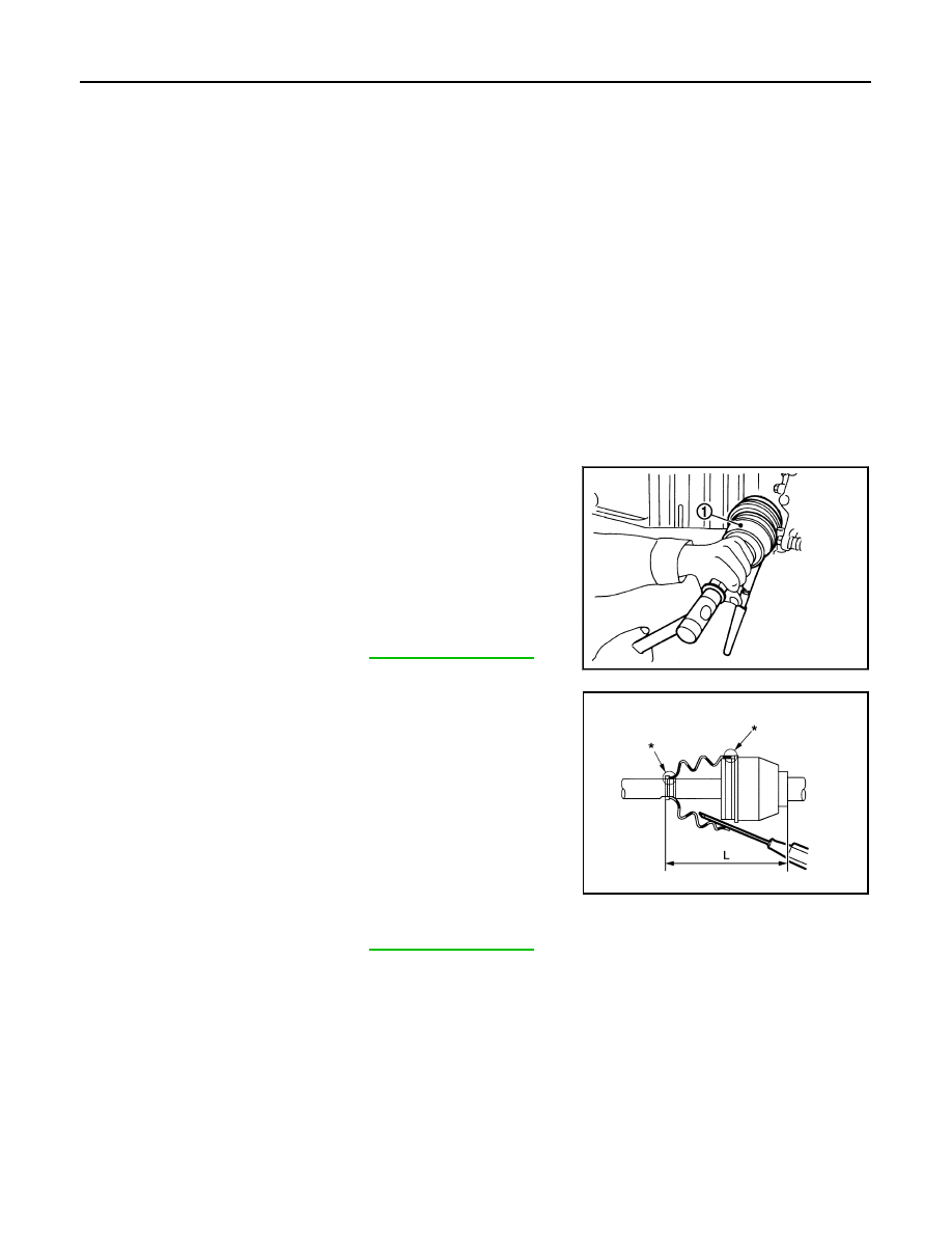
7.
Install joint sub-assembly (1) to housing assembly using plastic
hammer.
CAUTION:
Confirm that joint sub-assembly is correctly engaged while
rotating drive housing assembly.
8.
Apply the specified amount of grease into the boot inside from
large diameter side of boot.
9.
Install the boot securely into grooves (indicated by “*” marks)
shown in the figure.
CAUTION:
If grease adheres to the boot mounting surface (indicated
by “*” mark) on the housing assembly or joint sub-assem-
bly, boot may be removed. Remove all grease from the boot
mounting surface.
10. To prevent the deformation of the boot, adjust the boot installa-
tion length (L) to the specified value shown below by inserting
the suitable tool into inside of the boot from the large diameter
side of the boot and discharging the inside air.
CAUTION:
• If the boot installation length exceeds the standard, it may cause breakage of boot.
• Be careful not to touch the inside of the boot with a tip of tool.
Standard
Grease amount
: Refer to
.
JPDIF0011ZZ
Standard
L
: Refer to
.
JPDIF0222ZZ
Revision: 2008 October
2009 Murano