Nissan Murano Z51 (2008 year). Manual - part 192
EXL-180
< ON-VEHICLE REPAIR >
[XENON TYPE]
HAZARD SWITCH
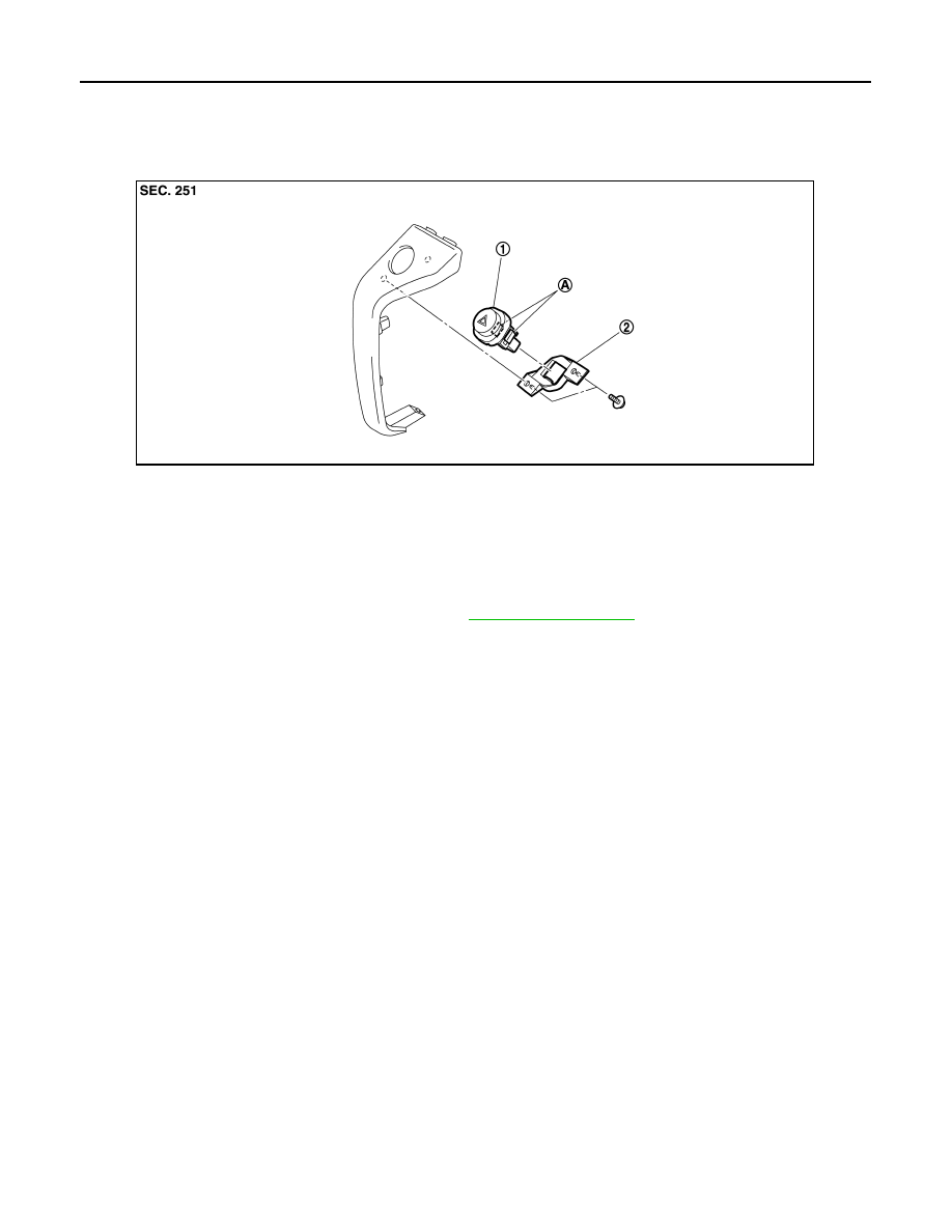
HAZARD SWITCH
Exploded View
INFOID:0000000003261383
Removal and Installation
INFOID:0000000003261384
REMOVAL
1.
Remove the instrument stay cover (RH). Refer to
.
2.
Remove the screws. And then remove the switch bracket from the instrument stay cover.
3.
Remove the hazard switch.
INSTALLATION
Install in the reverse order of removal.
1.
Hazard switch
2.
Switch bracket
A.
Pawls
JPLIA0819ZZ
Revision: 2008 October
2009 Murano