Nissan Murano Z51 (2008 year). Manual - part 138
EC-24
< FUNCTION DIAGNOSIS >
[VQ35DE]
ENGINE CONTROL SYSTEM
JMBIA1832GB
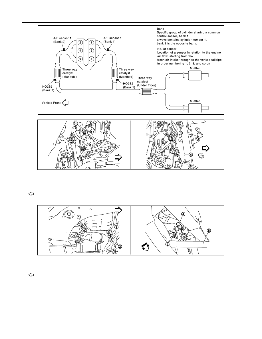
1.
A/F sensor 1 (bank 1) harness con-
nector
2.
A/F sensor 1 (bank 1)
3.
A/F sensor 1 (bank 2) harness con-
nector
4.
A/F sensor 1 (bank 2)
: Vehicle front
1.
HO2S2 (bank 1)
2.
HO2S2 (bank 2)
3.
HO2S2 (bank 2) harness connector
4.
HO2S2 (bank 1) harness connector
5.
Power steering pressure sensor
6.
Drive shaft (RH)
: Vehicle front
JMBIA1116ZZ
JMBIA1117ZZ
Revision: 2008 October
2009 Murano