Nissan Murano Z51 (2008 year). Manual - part 137
EC-8
< BASIC INSPECTION >
[VQ35DE]
DIAGNOSIS AND REPAIR WORKFLOW
BASIC INSPECTION
DIAGNOSIS AND REPAIR WORKFLOW
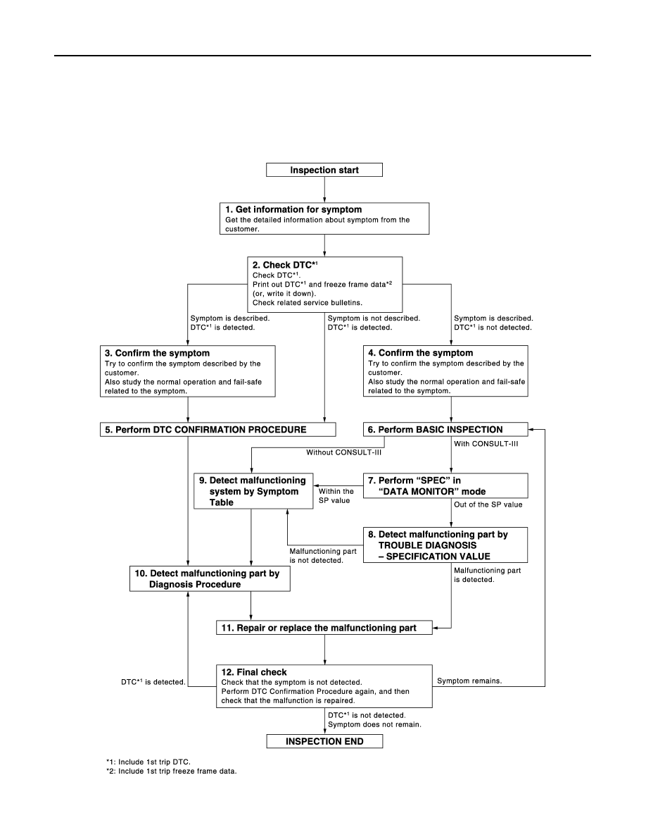
Work Flow
INFOID:0000000003387866
OVERALL SEQUENCE
DETAILED FLOW
JMBIA1416GB
Revision: 2008 October
2009 Murano