Nissan Murano Z51 (2008 year). Manual - part 134


  Index      Manuals     Nissan Murano Z51 (2008 year) - Service and Repair Manual


Search            copyright infringement  


Content      ..     132      133      134      135     ..


Nissan Murano Z51 (2008 year). Manual - part 134


SERVICE DATA AND SPECIFICATIONS (SDS)

DLN-83

< SERVICE DATA AND SPECIFICATIONS (SDS) 

[REAR PROPELLER SHAFT: 3F63A-EDJ75]

C

E

F

G

H

I

J

K

L

M

A

B

DLN

N

O

P

SERVICE DATA AND SPECIFICATIONS (SDS)

SERVICE DATA AND SPECIFICATIONS (SDS)

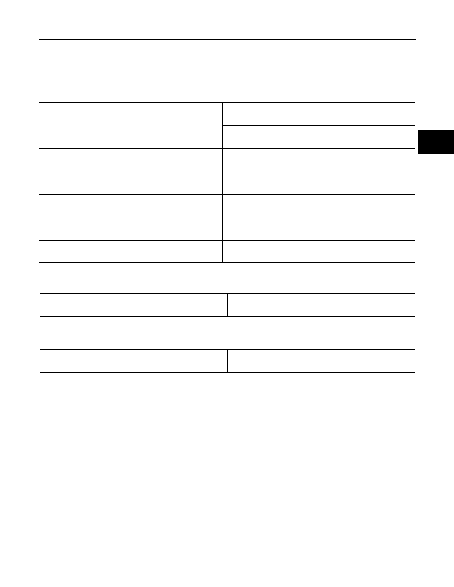
General Specifications

INFOID:0000000003412863

Propeller Shaft Runout

INFOID:0000000003412864

Unit: mm (in)

Journal Axial Play

INFOID:0000000003412865

Unit: mm (in)

Applied model

AWD

VQ35DE

CVT

Propeller shaft model

3F63A-EDJ75

Number of joints

3

Type of journal bearings
(Non-disassembly type)

1st joint

Shell type

2nd joint

EDJ type

3rd joint

Shell type

Coupling method with transfer

Flange type

Coupling method with rear final drive

Flange type

Shaft length

1st (Spider to EDJ joint center)

1142 mm (44.96 in)

2nd (EDJ joint center to spider)

987 mm (38.86 in)

Shaft outer diameter

1st

63.5 mm (2.500 in)

2nd

75 mm (2.95 in)

Item

Limit

Propeller shaft runout

0.8 (0.031)

Item

Standard

Journal axial play

0 (0)

Revision: 2008 October

2009 Murano

DLN-84

< FUNCTION DIAGNOSIS >

[REAR FINAL DRIVE: R145]

REAR FINAL DRIVE ASSEMBLY

FUNCTION DIAGNOSIS

REAR FINAL DRIVE ASSEMBLY

System Diagram

INFOID:0000000003412870

1.

Companion flange

2.

Electric controlled coupling

3.

AWD solenoid

4.

Center oil seal

5.

Pinion front bearing

6.

Collapsible spacer

7.

Pinion rear bearing

8.

Drive pinion

9.

Side gear

10. Pinion mate gear

11.

Drive gear

12. Pinion mate shaft

13. Side bearing

14. Differential case

JPDID0133ZZ

Revision: 2008 October

2009 Murano

NOISE, VIBRATION AND HARSHNESS (NVH) TROUBLESHOOTING

DLN-85

< SYMPTOM DIAGNOSIS >

[REAR FINAL DRIVE: R145]

C

E

F

G

H

I

J

K

L

M

A

B

DLN

N

O

P

SYMPTOM DIAGNOSIS

NOISE, VIBRATION AND HARSHNESS (NVH) TROUBLESHOOTING

NVH Troubleshooting Chart

INFOID:0000000003412866

Use the chart below to find the cause of the symptom. If necessary, repair or replace these parts.

×

: Applicable

Reference

DLN

-12

1,

 "

In

s

p

e

c

tion

 Af

ter Di

sa

ss

em

bl

y

"

DL

N-1

18,

 "

Adjustment

"

DLN

-12

1,

 "

In

s

p

e

c

tion

 Af

ter Di

sa

ss

em

bl

y

"

DL

N-1

18,

 "

Adjustment

"

DL

N-1

18,

 "

Adjustment

"

DLN

-90, "

In

sp

ectio

n

"

NVH in DLN section

NVH in F

AX, 

RAX, FSU and 

R

S

U sections

NVH in WT section

NVH in WT section

NVH i

n

 F

AX and RAX 

secti

o

n

NVH in B

R

 section

NVH in S

T

 section

Possible cause and SUSPECTED PARTS

Gea

r to

ot

h ro

ug

h

Ge

ar co

nt

a

ct

 im

pro

p

e

r

T

o

o

th su

rfac

es

 wo

rn

Ba

ck

la

sh

 in

co

rrec

t

Com

p

ani

on

 fl

an

ge

 ex

ce

ss

iv

run

ou

t

Ge

ar oi

l im

pro

p

e

r

PROPELLER S

H

AFT

AXLE AND S

U

S

PENSION

TI

RE

ROAD WHEE

L

DRIVE SHAFT

BRAKE

STE

E

RING

Symptom

Noise

×

×

×

×

×

×

×

×

×

×

×

×

×

Revision: 2008 October

2009 Murano

DLN-86

< PRECAUTION >

[REAR FINAL DRIVE: R145]

PRECAUTIONS

PRECAUTION

PRECAUTIONS

Service Notice or Precautions for Rear Final Drive

INFOID:0000000003412867

• Check for the correct installation status prior to removal or disassembly. If matching marks are required, be

certain they never interfere with the function of the parts when applied.

• Overhaul should be done in a clean work area, it is preferable to work in dustproof area.
• Before disassembly, using steam or white gasoline, completely remove sand and mud from the exterior of

the unit, preventing them from entering into the unit during disassembly or assembly.

• Check appearance of the disassembled parts for damage, deformation, and unusual wear. Replace them

with a new one if necessary.

• Gaskets, seals and O-rings should be replaced any time when the unit is disassembled.
• In principle, tighten bolts or nuts gradually in several steps working diagonally from inside to outside. If tight-

ening sequence is specified, observe it.

• Clean and flush the parts sufficiently and blow-dry them.
• Be careful not to damage sliding surfaces and mating surfaces.
• When applying sealant, remove the old sealant from the mounting surface; then remove any moisture, oil,

and foreign materials from the application and mounting surfaces.

• Always use shop paper for cleaning the inside of components.
• Avoid using cotton gloves or shop rags to prevent entering of lint.
• During assembly, observe the specified tightening torque, and apply new gear oil, petroleum jelly, or multi-

purpose grease as specified for each vehicle, if necessary.

Revision: 2008 October

2009 Murano

PREPARATION

DLN-87

< PREPARATION >

[REAR FINAL DRIVE: R145]

C

E

F

G

H

I

J

K

L

M

A

B

DLN

N

O

P

PREPARATION

PREPARATION

Special Service Tools

INFOID:0000000003412868

The actual shapes of Kent-More tools may differ from those of special service tools illustrated here.

Tool number
(Kent-More No.)
Tool name

Description

KV38100200
(J-26233)
Drift
a: 65 mm (2.56 in) dia.
b: 49 mm (1.93 in) dia.

• Installing front oil seal
• Installing side oil seal

ST27861000
(

)

Drift
a: 62 mm (2.44 in) dia.
b: 52 mm (2.05 in) dia.

Installing front oil seal

ST35271000
(J-26091)
Drift
a: 72 mm (2.83 in) dia.
b: 63 mm (2.48 in) dia.

Installing center oil seal

KV40100610
(J-26089)
Drift
a: 63 mm (2.48 in) dia.
b: 54.3 mm (2.138 in) dia.

Removing and installing gear carrier and rear 
cover (2 pieces are used)

ST33052000
(

)

Drift
a: 22 mm (0.87 in) dia.
b: 28 mm (1.10 in) dia.

Removing side bearing inner race

KV4010520
(

)

Drift
a: 39.7 mm (1.563 in) dia.
b: 35 mm (1.38 in) dia.
c: 15 mm (0.59 in) dia.

Installing side bearing inner race

ZZA1143D

ZZA0832D

ZZA0814D

ZZA1000D

ZZA1023D

ZZA1133D

Revision: 2008 October

2009 Murano

DLN-88

< PREPARATION >

[REAR FINAL DRIVE: R145]

PREPARATION

KV38108500
(

)

Drive pinion socket

• Removing and installing drive pinion nut
• Measuring preload torque

KV38108400
(

)

Pinion nut wrench

Removing and installing drive pinion nut

ST17130000
(

)

Drift
a: 31.8 mm (1.252 in) dia.
b: 58 mm (2.28 in) dia.

Installing pinion rear bearing outer race

ST33230000
(J-25805-01)
Drift
a: 51 mm (2.01 in) dia.
b: 41 mm (1.61 in) dia.
c: 28.5 mm (1.122 in) dia.

Installing pinion front bearing outer race

ST23860000
(

)

Drift
a: 38 mm (1.50 in) dia.
b: 33 mm (1.30 in) dia.

• Installing pinion rear bearing inner race
• Installing pinion front bearing inner race

ST38220000
(

)

Press stand
a: 63 mm (2.48 in) dia.
b: 65 mm (2.56 in) dia.

Installing pinion front bearing inner race

Tool number
(Kent-More No.)
Tool name

Description

ZZA1205D

ZZA1206D

ZZA0836D

ZZA1046D

ZZA0534D

ZZA1058D

Revision: 2008 October

2009 Murano

PREPARATION

DLN-89

< PREPARATION >

[REAR FINAL DRIVE: R145]

C

E

F

G

H

I

J

K

L

M

A

B

DLN

N

O

P

Commercial Service Tools

INFOID:0000000003412869

ST3127S000
(J-25765-A)
Preload gauge

Measuring preload torque

KV381086S1
(

)

Dummy cover set
1. KV38108610
(

)

Dummy cover
2. KV38108621
(

)

Dummy cover spacer
3. KV38108630
(

)

Dummy cover shim

• Checking backlash
• Checking drive gear runout
• Checking tooth contact

Tool number
(Kent-More No.)
Tool name

Description

ZZA0503D

SDIA2313E

Tool name

Description

Flange wrench

Removing and installing companion flange 
lock nut

Power tool

Loosening bolts and nuts

NT771

PBIC0190E

Revision: 2008 October

2009 Murano

DLN-90

< ON-VEHICLE MAINTENANCE >

[REAR FINAL DRIVE: R145]

REAR DIFFERENTIAL GEAR OIL

ON-VEHICLE MAINTENANCE

REAR DIFFERENTIAL GEAR OIL

Inspection

INFOID:0000000003412871

OIL LEAKAGE

Check that oil is not leaking from final drive assembly or around it.

OIL LEVEL

• Remove filler plug (1) and check oil level from filler plug mounting

hole as shown in the figure.

CAUTION:

Never start engine while checking oil level.

• Set a new gasket on filler plug and install it on final drive assembly.

Refer to 

DLN-101, "Exploded View"

.

CAUTION:

Never reuse gasket.

Draining

INFOID:0000000003412872

1.

Stop engine.

2.

Remove drain plug (1) and drain gear oil.

3.

Set a new gasket on drain plug and install it to final drive assem-
bly and tighten to the specified torque. Refer to 

DLN-101,

"Exploded View"

.

CAUTION:

Never reuse gasket.

Refilling

INFOID:0000000003412873

1.

Remove filler plug (1). Fill with new gear oil until oil level reaches
the specified level near filler plug mounting hole.

2.

After refilling oil, check oil level. Set a new gasket to filler plug,
then install it to final drive assembly. Refer to 

DLN-101,

"Exploded View"

.

CAUTION:

Never reuse gasket.

JPDID0164ZZ

JPDID0163ZZ

Oil grade and viscosity

: Refer to 

MA-15, "FOR 

NORTH AMERICA : Fluids 
and Lubricants"

.

Oil capacity

: Refer to 

DLN-123, "Gen-

eral Specification"

.

JPDID0164ZZ

Revision: 2008 October

2009 Murano

FRONT OIL SEAL

DLN-91

< ON-VEHICLE REPAIR >

[REAR FINAL DRIVE: R145]

C

E

F

G

H

I

J

K

L

M

A

B

DLN

N

O

P

ON-VEHICLE REPAIR

FRONT OIL SEAL

Exploded View

INFOID:0000000003412874

Removal and Installation

INFOID:0000000003412875

REMOVAL

1.

Remove rear propeller shaft. Refer to 

DLN-80, "Exploded View"

.

2.

Put matching mark on the thread edge of electric controlled cou-
pling. The matching mark should be in line with the matching
mark on companion flange.

CAUTION:

For matching mark, use paint. Never damage electric con-
trolled coupling.

1.

Final drive assembly

2.

Front oil seal

3.

Companion flange

4.

Companion flange lock nut

A.

Oil seal lip

: Vehicle front

: Apply gear oil.

Refer to 

GI-4, "Components"

 for symbols not described above.

JPDID0004GB

PDIA0455E

Revision: 2008 October

2009 Murano

DLN-92

< ON-VEHICLE REPAIR >

[REAR FINAL DRIVE: R145]

FRONT OIL SEAL

3.

Remove companion flange lock nut, using a flange wrench
(commercial service tool). Then remove companion flange.

4.

Remove front oil seal from coupling cover, using a suitable tool.

CAUTION:

Be careful not to damage coupling cover.

INSTALLATION

1.

Install front oil seal until it becomes flush with the coupling cover
end, using the drifts.

CAUTION:

• Never reuse oil seal.
• When installing, never incline oil seal.
• Apply multi-purpose grease onto oil seal lips, and gear oil

onto the circumference of oil seal.

2.

Align the matching mark of electric controlled coupling with the
matching mark of companion flange, then install the companion
flange.

3.

Install companion flange lock nut with a flange wrench (commer-
cial service tool), tighten to the specified torque.

CAUTION:

Never reuse companion flange lock nut.

4.

Install rear propeller shaft. Refer to 

DLN-80, "Exploded View"

.

5.

When oil leaks while removing, check oil level after the installa-
tion. Refer to 

DLN-90, "Inspection"

.

JSDIA0199ZZ

JSDIA0200ZZ

A

: Drift [SST: KV38100200 (J-26233)]

B

: Drift [SST: ST27861000 (

)]

PDIA0038E

PDIA0455E

Revision: 2008 October

2009 Murano

SIDE OIL SEAL

DLN-93

< ON-VEHICLE REPAIR >

[REAR FINAL DRIVE: R145]

C

E

F

G

H

I

J

K

L

M

A

B

DLN

N

O

P

SIDE OIL SEAL

Exploded View

INFOID:0000000003412876

Removal and Installation

INFOID:0000000003412877

REMOVAL

1.

Remove rear drive shafts with power tool. Refer to 

RAX-15, "Exploded View"

.

2.

Remove side oil seals, using a suitable tool.

CAUTION:

Be careful not to damage gear carrier and rear cover.

INSTALLATION

1.

Install side oil seals until it becomes flush with the carrier end,
using the drift (A) [SST: KV38100200 (J-26233)].

CAUTION:

• Never reuse oil seals.
• When installing, never incline oil seals.
• Apply multi-purpose grease onto oil seal lips, and gear oil

onto the circumference of oil seal.

2.

Install rear drive shafts. Refer to 

RAX-15, "Exploded View"

.

3.

When oil leaks while removing, check oil level after the installa-
tion. Refer to 

DLN-90, "Inspection"

.

1.

Final drive assembly

2.

Side oil seal

A.

Oil seal lip

: Vehicle front

: Apply gear oil.

Refer to 

GI-4, "Components"

 for symbols not described above.

JSDIA0232ZZ

PDIA0431E

JPDID0183ZZ

Revision: 2008 October

2009 Murano

DLN-94

< ON-VEHICLE REPAIR >

[REAR FINAL DRIVE: R145]

ELECTRIC CONTROLLED COUPLING

ELECTRIC CONTROLLED COUPLING

Exploded View

INFOID:0000000003412878

Removal and Installation

INFOID:0000000003412879

REMOVAL

1.

Remove rear propeller shaft. Refer to 

DLN-80, "Exploded View"

.

2.

Disconnect AWD solenoid harness connector.

3.

Remove connector bracket.

4.

Put matching mark on the thread edge of electric controlled cou-
pling. The matching mark should be in line with the matching
mark on the companion flange.

CAUTION:

For matching mark, use paint. Never damage electric con-
trolled coupling.
NOTE:
When replacing electric controlled coupling, matching mark is
not necessary.

1.

Final drive assembly

2.

Center oil seal

3.

AWD solenoid harness

4.

Electric controlled coupling

5.

Coupling cover

6.

Reamer bolt

7.

Connector bracket

8.

Front oil seal

9.

Companion flange

10. Companion flange lock nut

A.

Oil seal lip

: Vehicle front

: Apply gear oil.

: Apply Genuine Silicone RTV or equivalent. Refer to 

GI-17, "Recommended Chemical Products and Sealants"

.

Refer to 

GI-4, "Components"

 for symbols not described above.

JSDIA1026GB

PDIA0455E

Revision: 2008 October

2009 Murano

ELECTRIC CONTROLLED COUPLING

DLN-95

< ON-VEHICLE REPAIR >

[REAR FINAL DRIVE: R145]

C

E

F

G

H

I

J

K

L

M

A

B

DLN

N

O

P

5.

Remove companion flange lock nut, using a flange wrench
(commercial service tool).

6.

Remove companion flange.

7.

Remove electric controlled coupling breather hose from cou-
pling cover.

8.

Remove coupling cover with electric controlled coupling from
final drive assembly.

9.

Remove electric controlled coupling from coupling cover.

10. Remove AWD solenoid harness.

11. Remove front oil seal from coupling cover, using a suitable tool.

CAUTION:

Be careful not to damage coupling cover.

12. Remove center oil seal from final drive assembly.

INSTALLATION

1.

Using the drift (A) [SST: ST35271000 (J-26091)], install center
oil seal (1) as shown in the figure.

CAUTION:

• Never reuse oil seal.
• When installing, never incline oil seal.
• Apply multi-purpose grease onto oil seal lips, and gear oil

onto the circumference of oil seal.

2.

Connect AWD solenoid harness to electric controlled coupling.

JSDIA0199ZZ

PDIA0458E

PDG0213D

D

: 0.8 – 1.2 mm (0.031 – 0.047 in)

JSDIA0260ZZ

Revision: 2008 October

2009 Murano

DLN-96

< ON-VEHICLE REPAIR >

[REAR FINAL DRIVE: R145]

ELECTRIC CONTROLLED COUPLING

3.

Install electric controlled coupling to spline of drive pinion inside
gear carrier.

CAUTION:

• Align the pin on electric controlled coupling with the

groove of gear carrier.

• Be careful not to damage center oil seal.

4.

Set AWD solenoid harness guide to gear carrier.

5.

Using the drifts, drive front oil seal until it becomes flush with the
coupling cover end.

CAUTION:

• Never reuse oil seal.
• When installing, never incline oil seal.
• Apply multi-purpose grease onto oil seal lips, and gear oil

onto the circumference of oil seal.

6.

Apply liquid gasket to mating surface of coupling cover. Overlap
both ends of the bead for at least 3 mm (0.12 in).
Use Genuine Silicone RTV or equivalent. Refer to 

GI-17, "Rec-

ommended Chemical Products and Sealants"

.

CAUTION:

Remove old gasket adhering to the mounting surfaces.
Also remove any moisture, oil, or foreign material adhering
to the mounting surfaces.

7.

Install coupling cover to final drive assembly with arrow facing
upward, temporarily tighten reamer bolts to the positions shown
in the figure.

8.

Tighten reamer bolts and coupling cover mounting bolts to the
specified torque.

9.

Install electric controlled coupling breather hose to coupling
cover.

10. Install connector bracket, and tighten bolts to the specified

torque.

11. Connect AWD solenoid harness connector.

12. Install companion flange.

NOTE:
When reusing electric controlled coupling, align the matching
mark of electric controlled coupling with the matching mark of
companion flange, then install companion flange.

13. Install companion flange lock nut with flange wrench (commer-

cial service tool), tighten to the specified torque.

CAUTION:

Never reuse companion flange lock nut.

14. Check companion flange runout. Refer to 

DLN-104, "Adjust-

ment"

.

PDIA0463E

A

: Drift [SST: KV38100200 (J-26233)]

B

: Drift [SST: ST27861000 (

)]

PDIA0449E

PDIA0613E

SDIA0587E

PDIA0455E

Revision: 2008 October

2009 Murano

ELECTRIC CONTROLLED COUPLING

DLN-97

< ON-VEHICLE REPAIR >

[REAR FINAL DRIVE: R145]

C

E

F

G

H

I

J

K

L

M

A

B

DLN

N

O

P

15. Install rear propeller shaft. Refer to 

DLN-80, "Exploded View"

.

16. When oil leaks while removing, check oil level after the installation. Refer to 

DLN-90, "Inspection"

.

Revision: 2008 October

2009 Murano

DLN-98

< REMOVAL AND INSTALLATION >

[REAR FINAL DRIVE: R145]

REAR FINAL DRIVE ASSEMBLY

REMOVAL AND INSTALLATION

REAR FINAL DRIVE ASSEMBLY

Exploded View

INFOID:0000000003412880

Removal and Installation

INFOID:0000000003412881

REMOVAL

1.

Remove rear propeller shaft. Refer to 

DLN-80, "Exploded View"

.

2.

Remove stabilizer bar. Refer to 

RSU-15, "Exploded View"

.

3.

Remove EVAP canister. Refer to 

EC-549, "Exploded View"

.

4.

Disconnect rear drive shafts (final drive side). Refer to 

RAX-15, "Exploded View"

.

5.

Disconnect AWD solenoid harness connector.

6.

Remove rear final drive breather hose and electric controlled coupling breather hose.

7.

Support final drive assembly with a suitable jack.

8.

Remove rear final drive mounting nut (

) at rear suspension

member.

1.

Final drive mounting bracket

2.

Washer

3.

Dynamic damper assembly

4.

Final drive assembly

: Vehicle front

Refer to 

GI-4, "Components"

 for symbols in the figure.

JPDID0162GB

JPDID0171ZZ

Revision: 2008 October

2009 Murano


Content      ..     132      133      134      135     ..