Nissan Murano Z51 (2008 year). Manual - part 115
DLK-372
< ON-VEHICLE REPAIR >
[WITH INTELLIGENT KEY SYSTEM]
OUTSIDE KEY ANTENNA
OUTSIDE KEY ANTENNA
DRIVER SIDE
DRIVER SIDE : Exploded View
INFOID:0000000003318264
DLK-331, "DOOR STRIKER : Exploded View"
.
DRIVER SIDE : Removal and Installation
INFOID:0000000003318265
REMOVAL
Remove the front outside handle LH. Refer to
DLK-354, "OUTSIDE HANDLE : Removal and Installation"
INSTALLATION
Install in the reverse order of removal.
PASSENGER SIDE
PASSENGER SIDE : Exploded View
INFOID:0000000003318266
DLK-331, "DOOR STRIKER : Exploded View"
.
PASSENGER SIDE : Removal and Installation
INFOID:0000000003318267
REMOVAL
Remove the front outside handle RH. Refer to
DLK-354, "OUTSIDE HANDLE : Removal and Installation"
.
INSTALLATION
Install in the reverse order of removal.
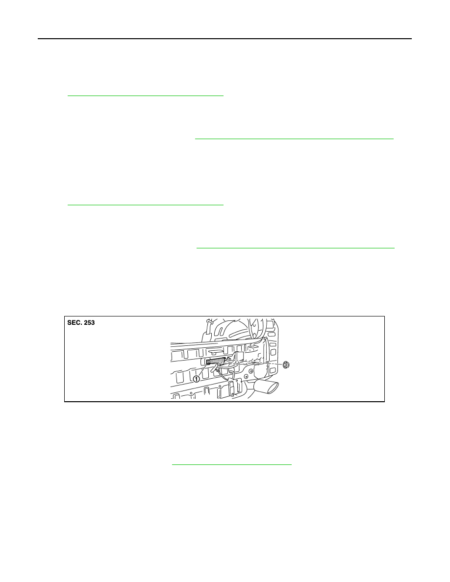
REAR BUMPER
REAR BUMPER : Exploded View
INFOID:0000000003318268
REAR BUMPER : Removal and Installation
INFOID:0000000003318269
REMOVAL
1.
Remove the rear bumper. Refer to
EXT-15, "Removal and Installation"
1.
Outside key antenna (rear bumper)
JMKIA2179ZZ
Revision: 2008 October
2009 Murano